I like FETs as much as the next engineer but if you're going to write about them, try to not make things worse.
In particular, this made me sad: the 10K resistor to ground isn't strictly necessary, but it ensures that the MOSFET remains OFF if the arduino is disconnected or it's pin is not an OUTPUT.
I was helping a high school student with a transistor project and he was complaining that "half the FETs he bought were 'bad'". And they weren't really bad, but they were destroyed. They were destroyed because, like our author, the student had no understanding of how the FET worked and so didn't realize that when you exceed the maximum Gate voltage on a FET it generally causes a current to "jump the gap" to the source and that permanently breaks it. What is even more, since the gate is essentially a capacitor, you can just touch the gate with your finger and pass enough charge (without feeling a shock or anything) to greatly exceed the gate voltage. Pick up the FET without being grounded and "boom!" dead FET.
Now there is almost no way to generate enough current by touching a Bipolar transistor to kill it, and so they continue to work for a long time while plugging them in and out of breadboards.
Do they dissipate more power? Absolutely. Are they difficult to run in parallel? Sure. But they are pretty robust parts. Sort of like the difference between alkaline batteries and LiON rechargeable batteries. Sure the latter are a "better" choice, you can recharge them after all, but if you use them wrong they catch on fire, if you short an alkaline battery it gets hot but doesn't go ballistic on you.
So those "antique" parts are generally very cost effective, very robust, and easy to get. So they make excellent tools to teach you the basics. Do you want to stay with them as you get more advanced? Probably not, but you're probably not skiing on the same skis you learned on either.
Yep. It is indeed easy to ruin a FET with minuscule amount of static charge. That is, unless there is a zener (or two, back-to-back) connecting gate to source. Many modern FETs have this built right in. E.g. ATP214 [1].
That does sound like a very useful part for learning purposes, as well as general robustness, but they don't appear to be particularly common. I get no results on eBay, nor can I find through-hole packages.
Surface mount only (like most modern transistors), but SOT-23 isn't too hard to hand solder. There are lots of breakout boards for surface mount packages available for prototyping, or you could even solder some mod wire directly to each pin and put some hot melt glue on it to keep it in place.
When I buy 100 BS170 MOSFETs, I also buy 100 9.1v Zener diodes for this precise reason. Gate protection diodes are essential for peace of mind when using MOSFETs.
>In particular, this made me sad: the 10K resistor to ground isn't strictly necessary, but it ensures that the MOSFET remains OFF if the arduino is disconnected or it's pin is not an OUTPUT.
Not sure why that made you sad (extraneous ' in its?).
But I agree about the static-sensitive disadvantage of MOSFETs.
Also, the author mentions that a TIP120 is not a transistor but a darlington pair (two transistors in one) but then misstates the Hfe.
The whole point of a darlington is to get a high Hfe (small base current controlling large collector current) and the Min. Hfe is 1000, at least according to:
It wasn't the grammar :-) it was that the author considered the 10K resistor to ground as "not strictly necessary". It is critical if the microprocessor pin can float (tri-state). Without it, and a floating gate, not only will the FET eventually turn on, it can be damaged by excess charge build up.
Not just excessive charge up it could be possible for it to be stuck in its linear region and dissipate a lot of power as it's spuriously turning on because there's a charge on the gate. I've managed to do that one on accident with a bad motor driving circuit. Though it was also largely caused by coupling on the breadboard.
nit: It's not wrong to assert that the microcontroller software will prevent the output pin from ever floating. And the gate's voltage will be constrained between Vdd and Vss due to the output pin's likely body diodes. Is it worth it to save a penny part, especially in a hobby/prototype design? No.
Also if you throw away all your BJTs, what do you use to drive the gate capacitance of your fancy FETs?
I build a lot of guitar effects, and that community is even worse when it comes to attachement to obsolete components. The discontinuation of J201 JFETs (in TO-92 through hole package at least) by Fairchild has caused a lot of upset. My perspective, not widely shared, is that JFETs in general have been made obsolete by depletion-mode MOSFETs, at least in audio circuits.
Part of the reason, I think, is that a lot of "designers" of guitar pedals don't understand the math that determines component values for a particular transistor in a particular circuit so they don't know how to either select a modern transistor to replace an obsolete one based on datasheet parameters or to change the collector / emitter / source / drain / etc resistor values to work right with a new part.
My immediate response was: "That looks like a really great amp from the mid 1980's--looks like it was designed by someone who actually understands electrical engineering. It should have a pretty clean. But if you overdrive it, the clipping on those JFET's is gonna sound like fscking buzzsaw trash."
He, of course, laughed knowing that Dimebag Darrell used the amp for precisely that buzzsaw sound. You would have to add lots of "clipping" components to get the same sound out of depletion mode MOSFET's.
Now, whether that's a good sound is open to debate. :)
There definitely are people who want that buzzsaw sound. The Boss HM-2 pedal "chainsaw" sound is also having a moment right now. I'm not really into either, but I do like really saturated high gain sounds with a lot of compression.
ADC, MCU, DAC, done.
Cheaper, too -- I think 50 cent ARMs can do that these days.
Any pedal that isn't digital today is just nostalgia (like tube headphone amps and the like.)
Digital is the clear better choice even for sound shaping.
Hogwash. There are effects that analogue clearly destroys digital on. And the main one is distortion.
Digital is much more suited to time based effects. Analogue to harmonic distortion based effects.
You can keep your ADC/MCU/DAC distortion pedal. But if you are ever wondering why your guitar distortion sounds crap, this is it. But maybe you think it's fine. Anything sounds great with cotton-ears.
And tube amps only being for nostalgia? I wan't you to take your guitar, your digital distortion pedal and your digital amplifier and go to a rehearsal room with another guitarist who uses analogue distortion and a tube amp. Turn them both up loud. Jam together. Compare the tones. Compare the nature of how your amplifiers respond to your tone.
Sitting in your bedroom playing by yourself will never convince you of the short comings of your digital rig.
I'm more of a recording engineer than a guitarist (member of the AES for many years.)
Shitty digital pedals from 20 years ago sound shitty, I agree!
Well modelled digital effects, however, can these days give you anything an analog pedal can. Most of the time, just run a high accuracy Spice model of the pedal in real time! Modern DSP is so cheap and fast that this is possible and works fine.
It's definitely a straightforward and cost-effective circuit to build. The real cost (and test) is in the DSP programming. There's a reason a Fractal Axe-FX or Kemper Profiler is so expensive, and it's not the bill of materials. Electro-Harmonix sells a lot of DSP based pedals like the POGs and the B9/C9/M9 series, but I'd bet it's a small fraction of the number of Big Muffs they move, which they don't seem to be in any hurry to digitize. It's a lot easier to capture the sound of a '70s Big Muff by just building a Big Muff circuit than by programming a simulation of one.
Lest you think I'm some kind of analog purist, I'm actually currently building a batch of pedals for sale that use an AVR MCU an its internal ADC to generate 3 different octaves of square wave output.
> ADC, MCU, DAC, done. Cheaper, too -- I think 50 cent ARMs can do that these days.
And yet smart engineers keep using Analog Devices SHARC DSP's for effects on audio interfaces.
So SOMETHING must not be quite as simple as your claim.
(The answer is that most of these guitar effects are VERY non-linear and simulating non-linear stuff digitally is very much NOT straightforward in real-time.)
not smart, but old school and embedded in big companies
Devkit alone is >$1K and you wont be able to do anything with it without couple of $K in software and maybe even support contract. All that for ~$10 Arm Soc performance.
Its not really that simple.
Does the 50 cent ARM have accelerated floating point (though 32-bit fixed point is usually fine)?
Does the analog design have a realizable digital model (not always possible/practical with non-linear systems)?
Can a 50 cent ARM run the digital model at a high sample rate (needs to be 4-8x higher than normal audio rates to be able to filter out aliasing)?
Nostalgia sells, yet another 'that digital crap' pedal may not. And many, many guitar players are dead keen on recreating classic tones of the 60's and 70's with period-authentic designs.
Guitar d00ds having obscure, nonsensical reasons for things because "mah tones!"? Say it ain't so.
I mean, nearly every tube head on the market has an essentially pointless standby/bypass switch because of the mistaken belief that you need to warm up your tubes for some arbitrary amount of time in a modern amp and keep them warm.
I forget which manufacturer it was that dropped the switch on one model and saw sales plummet and got freaked out support calls asking why the switch wasn't there. Next iteration had the switch back.
Back in the 70's, a friend of mine created a formula where the inputs were number of switches, number of dials, and number of meters and would output the price. It was remarkably close at predicting the price of most any stereo receiver/amplifier in the stereo store.
One standout anomaly was the Heathkit 250W amp, which just had an on/off switch and 2 meters.
I wouldn't say they're pointless but more of a convenience than a necessity in most modern designs. Probably more important in vintage amps with old tubes and such where folks generally want to be more gentle and preserve the life of the tubes. Either way depends on the amp & circuit and you're right in many cases aren't needed.
Well tube amps do actually need to warm up, but people think it takes minutes to hours for them to warm up when it really takes like 2 to 5 seconds. That, I think, comes from a lack of knowledge about how tubes work and the general cargo cult surrounding sound electronics.
I never include a standby switch if I build a tube head from scratch, but when I build out of a "donor amp"* that has one I keep it, because it's at least useful as a mute switch.
*Using a cheap tube amp from CL as the basis for a new build and tossing everything except the chassis and transformers, and maybe the sockets if they are chassis mounted, is a great way to build a great sounding tube amp on the cheap.
Non-solid-state electron systems should be expected to have their own idiosyncracies, regardless of whether superstition is building up faster than it is being dissipated.
The regular ordinary procedure for cold-starting high-power vacuum tube systems is to switch on the unit while the tubes are in standby.
This will allow the cathodes to heat to their characteristic glow, fully developing the ability to deliver the current you will soon be demanding.
But no high voltage is applied to the anodes (there will be no sound from audio systems) until removed from standby.
A minute or two later is good.
If the cathodes are too cold when applying the high anode voltage, especially at high current demands, it can strip the cathodes of their ability to provide the full performance when you need it most in the future.
Small tubes, most preamp types, run on lower voltages and currents, don't suffer noticeably, and were cheap to begin with.
It's the bigger more expensive tubes that standby is for.
Shut down by switching to standby while the main unit is still powered on.
After no more than a minute or two, fully power off the unit unless you would otherwise have to cold-start unreasonaby soon afterward. This is about 10 to 20 minutes for popular audio units, or much more if there is a true need for instant-on over a longer term.
24 hour standby is not very good for the tubes either, best fully powered off to save hours, or idling at a reasonable fraction of their ratings.
On standby tubes are still more vibration sensitive than fully cold, so it's seldom a good idea to leave them on standby while there is a source of strong vibration from other sources.
Never leave a tube amp in direct sunlight unless fully powered off. Standby will not save you.
If it is allowed to heat up above ambient for any reason, let it cool back down to ambient before powering up.
Gear that can run continuously at ambient 100degF can die at 70degF in the sun.
Without the sun, different gear (including differing power bias settings on the same gear) will have different maximum ambient temperatures beyond which only short-term operation is advisable, even for units which are otherwise capable of continuous operation under slightly milder conditions.
For musicians it's the class of thick-cone reinforced speakers that can take 20 or 30 minutes (near their power rating) to break in every time, that can throw you off.
Speakers can not be "warmed up" silently, you have to make some noise.
After this cranked-up break in, reach into an open-back cab and you feel how hot the magnets are, they were made for this but not in the sun either, especially closed-back cabinets where you can't touch the magnets but you know they're even hotter.
But often it's not the warmth of the magnets (or the tubes) that makes a (beneficial) difference in the tone, it's the preflexing of the cones which makes them more articulate afterward.
Most amps themselves warm up way faster than that, and can do it silently.
I'm a noob builder (constructed my first pedal a week ago, woo) but I can kinda understand this. Most effects tend to overdrive their components. This by definition means that they operate beyond what a datasheet and the manufacturer specifies. Tiny differences that aren't noticeable when going by the specs can become much more obvious when hearing it overdriven.
Yes, the community is really based in "older is always better" kind of mentality, but there is a reason some old components are so valued, and why respected pedal manufacturers commonly hand-pick parts that meet their designed specs best (especially fuzz and overdrive effects), and this includes everything from picking transistors with ideal leakage etc, to hand picking resistors (though the resistor bit I'm not sure on why they don't just buy high precision ones for a few cents more)
There's a difference between overloading components and overdriving them. If you overdrive an amplifier (the circuit element, not the finished product) all you are doing is presenting it with an input signal with a greater amplitude than it can faithfully reproduce at the output, causing it to distort. It can still be operating perfectly happy within the manufacturer's specs as stated on the datasheet. I think you're thinking of overload, which isn't something you would typically find or hear outside of a power amp stage, typically a valve one.
> (though the resistor bit I'm not sure on why they don't just buy high precision ones for a few cents more)
high precision resistors can get expensive, aren't always readily available (depending on your volume), or simply might not be available in the power rating you need. especially if you don't need absolute precision you might consider it wasteful. so it's good to know how to match resistors when you're designing/prototyping the circuit.
because of that, it's probably become hearsay and superstition, and is consequently overused.
True but i think a lot of that is in adherence to the original design/specs they're emulating (or straight up ripping off). Folks went nuts over the XVive BBD revivals or even still pay ridiculous sums for original panasonics. Sometimes there simply aren't alternatives to achieve the same circuit or you're repairing something very specific (although that's probably outside the scope of the article's PoV).
As well there's the vintage issue...Sure, I buy NOS caps from the 50-70s for guitar tone circuits. I doubt side by side they sound noticeably better but if you're building vintage it only makes sense to keep the 'tronics true to the time period.
> I doubt side by side they sound noticeably better but if you're building vintage it only makes sense to keep the 'tronics true to the time period.
In vintage radio repair, they sometimes will replace old caps (usually electrolytics) with new ones, but put the new ones inside the old cans - to preserve the look of the device.
Obviously, though, this won't work with all parts...
This works well with electrolytic caps because modern ones are so much smaller for the same voltage and capacitance rating than older ones were.
You can also hollow out old carbon comp resistors and put metal film resistors inside them. As a bonus you could use resistor shells on the outside with color bands that don't at all represent the actual value of the resistor inside as a practical joke on anyone trying to clone the circuit.
Old car dash instruments are often upgraded the same way. They use new parts to drive the original indicators so it all looks correct, but is actually accurate.
There are even kits to replace the guts of old car radios with modern stereos while preserving the controls and dials and their function.
Speaking of cars, I know I've heard of people who restore old tube-based car radios replacing the "buzzer" (or whatever it's called) that boosts the battery voltage up to the "B" voltage (I think that's right) with something more "modern" (probably a 555 oscillator and some other parts); the metal can for the original part is more than roomy enough for the replacement, and the new stuff is more reliable.
On my '72 Dodge, there's a mechanical device to lower the 12 volt system voltage to 5 volts for the dash instruments. It's a buzzer kind of thingy. Some people replaced it with a modern voltage regulator to get exactly 5 clean volts, and found that the instruments didn't work right.
It turns out that the instruments needed the erratic 5 volts, else they'd "stick".
JFETs main application these days is for when you need very low noise, usually for precise measurements. A depletion mode MOSFET has similar behavior, but not specs.
Yeah, I see them used for that purpose and for VHF / UHF applications. A lot of precision op-amps also have JFET inputs. In guitar effects land JFETs are popular because as a class-a amplifier in common source configuration they bias the same way that a triode does. Ironically when people try to replicate tube preamp circuits by cascading JFET stages the result is anything but "very low noise". Depletion-mode MOSFETs can be cascaded like triodes without creating unacceptable (for a guitar pedal) noise levels.
Separate from my other comment.
I'm pretty much switched over entirely to AxeFX for my guitar & bass setup these days but I've been building circuits lately and figure instrument & vocal effects would be cool projects.
These days I'm mainly playing through my PC (Decent USB interface for input, my stereo via a good DAC for output).
I've got a decent tube combo amp, but it's just easier and more flexible to do it digitally. I mostly run S-Gear, which I find has by _far_ the best amp modeling, it's the only VST that really gets moderate overdrive right.
Depletion MOSFETs seem to have availability problems. My local distributors only have a dozen or so models, mostly SOT-23. I can see why DIYers are not all over them.
It's definitely true that there just aren't nearly as many depletion mode parts as there are enhancement mode. I've never tried getting them from anywhere other than Mouser. For my purposes I stick with LND150s and DN25XX / DN35XX parts.
There is nothing wrong with bipolar transistors. They aren't antiquated. FETs have definitely overtaken them in power applications (for good reason) but it seems hard to displace them for small signal applications. Small signal FETs just aren't that plentiful or cheap. There are many instances where a small signal FET makes sense (level translators, etc) but the cost doesn't justify its use. Using a 2n2222 and the like is appropriate.
On top of that, BJTs excel in many analog applications. There is a good reason why many analog IC companies make parts using a BiCMOS process. If you are doing a discrete analog design (generally for performance reasons) you often need the performance of BJTs or JFETs.
The article seems mostly right when it's about interfacing logic circuits with loads that require even moderate currents. FET is king in this field.
I've a little aquarium and I've noticed how fish always get scared when lights turn suddenly on or off. So I took an Arduino and wrote a timer app for it, using PWM to slowly drive the output up over 60 minutes (sunrise), keep it at max for a few hours, then drive it down slowly over 60 minutes (sunset). I used a MOS-FET to drive the power LEDs directly from the Arduino. Works fantastic, and the FET is cold at all times. A 2N3055 would have been pretty hot most of the time.
I've been playing with electronics for a few decades now, so I can't be accused of change for the sake of change. The old stuff still works, sure, but there are new toys which are better in some cases.
The problem with the article is that there is no nuance. Some beginner is going to read it and think all BJTs are bad, but that isn't even remotely true. It all depends on application.
I would certainly use MOSFETs for lighting (a power application). I probably wouldn't design an analog front-end for a specialized sensor with them though.
There is a purpose-designed Chinese chip exactly for your situation - control brightness of a LED strip based on PWM input. Compared to a bare MOSFET, this chip gives you higher efficiency, current-controlled (i.e. flicker-free) output and ability to drive LEDs directly (without current-limiting resistors).
PT4115, pretty cheap on ebay and other usual places.
Well, the LED strip I use is a black box (from an electrical perspective). It just needs 12V, no external resistors.
So I just hooked it up to 12V via the MOS-FET. The PWM signal from the Arduino (plugged into the MOS-FET) does the job of changing the apparent brightness.
Your ledstrip probably also consumes about 15 watts per meter since integrated current limiting resistors dissipate most of the energy; a black box with the efficiency of a lightbulb.
If you properly drive a 2N3055 (so all the way to 'on' or all the way to 'off') you'd have to put a pretty good current through it to get it to get hot. The trick is to use the highest voltage you can get away with (most power for the least amount of current). .6V * quite a few amps before you overcome the housings capacity to get rid of the heat.
You'll need to properly drive it though and not at too high a frequency (and for obvious reasons, not too low either because you'll notice the flicker).
> before you overcome the housings capacity to get rid of the heat.
The thing is, most of these larger BJT parts were designed to be used with heatsinks, not usually standalone. IMHO, there's nothing wrong with dropping some voltage and dumping some heat. Sure, it isn't efficient, but if you size everything properly, and your project can accommodate the heatsink - then where's the problem?
Heck, a long time ago you could get tiny heatsinks for some of the small round metal-can transistors that existed - I've got an old 16K minicomputer core-memory board from the 1970s that has drive electronics set up like this.
The author of this "rant" mentions not using L298 (and presumably the L293) either - but there's nothing wrong with these parts for hobbyists (outside of the L298's weird footprint, and the fact that heatsinks for them are almost unobtanium) - provided that the limitations are kept in mind (finding a low-cost mosfet 4A h-bridge in a thru-hole design is virtually impossible). These parts were originally meant for automotive applications, where having a 12-14V large amperage battery supply was the norm (people trying to use them for circuits with 6V or less always wonder why their small motors won't turn).
True, but there were some nice finned Multiwatt-15 heatsink profiles out there back in the day that looked nice. Sometimes they can be found NOS - but it's rare...
What frequency are you PWMing at, and are you applying any analog filtering? I frequently get annoyed by slow PWMed lighting, and I wonder how other animals with possibly faster vision perceive it.
If I count as a critter, I can easily tell the difference by moving my eyes and seeing the phantom array effect. If you're already using resistors for current limiting then putting a big enough capacitor across the LEDs will filter them without much difference in power consumption. I have no idea if the fish will care.
That effect drives me nuts too; but it seems to bother a minority of people. I've always assumed/guessed it's in the order of 50–100Hz; the 500–1000Hz mentioned may be fast enough to appear continuous to sensitive humans and maybe fish...
The most usual source of that flicker these days is driving LEDs (usually in a string of Christmas lights) with half-wave rectified AC, which can be considered PWM with a 50% duty cycle over the same period as the input signal - 60Hz in the US and I think Japan, 50Hz most other places. That's slow enough to see easily; it would surprise me to learn that PWM at ten times the rate is slow enough to see at all.
Looking at the code I wrote a while back to drive a four-digit common-cathode LED display (you know, a TV bomb timer!) as a clock, I find that after all the tuning I did to get rid of flicker, I ended up activating each digit for 1ms at a time. Granted, running under Raspbian this is going to flicker anyway from time to time because multitasking, but that aside, I found no PWM flicker perceptible, even at what is effectively 20% duty cycle over a 5ms period. (The decimals are implemented as a fifth "digit".) So I'm going to guess that .5KHz and up are fine for most humans. Fish I don't know about; (1) cites a flicker fusion rate between 2 and 40Hz for swordfish, but for goldfish I've no idea, other than to guess that .5KHz and up is probably fine for them too.
In my own testing I could see flicker at 10kHz, during fast eye movement only. This has nothing to do with flicker fusion threshold. Instead it's a failure of saccadic masking. At 10kHz it's subtle enough that it's not at all annoying, but I do find 1kHz slightly annoying. The commonly used 200Hz is definitely annoying.
I find it useful to speed up the default Arduino PWM by changing the clock source. There are some useful details at http://www.righto.com/2009/07/secrets-of-arduino-pwm.html . Basically you should be able to drive it up to tens of KHz. I'm not sure how far up it remains linear but works well enough for lighting.
At default clock rates (clock/256) I can definitely see the flicker, especially through the lowest duty cycles.
Higher gate capacitance of FETs is also a drawback. Often you need a bjt or even dedicated gate-driver IC to drive the gates quickly. The extra pole can also make negative feedback more complicated. And there's less component choice when you want more control in the ohmic region versus switching - for a non emitter/source follower circuit. Another issue is the higher gate voltages required - compared with bjts even using logic-level FETs.
The article would have been much better with a different title - "How to use FETs effectively and when to use them", not a binary oppositioning of "antique" versus "modern".
2n7000, BS270 are both pretty cheap for small signal FET applications.
For analog applications, BJTs are still very much important, but for digital stuff (and especially power stuff), it is usually easier to grab a cheap FET than use a BJT.
If you want to switch power, MOSFETs are the way to go today. Voltage drop is near zero.
Digi-Key has over a thousand MOSFETs in TO-220 packages. Here's one of the cheapest with a low gate threshold.[1] Probably good enough for most Arduino on/off applications.
MOSFETs do have some problems. They can draw large gate currents for the first few nanoseconds of turn-on, which can overload whatever is driving them. The gate input is very vulnerable to electrostatic discharge during handling. Device failure tends to be into the ON state.
I just went through a big struggle with MOSFET selection for a special purpose switching power supply. The big through-hole parts have too much gate capacitance and need too much drive at turn-on. Only in surface-mount could I get something that would work.
That's the real problem with antique parts. The new stuff is surface-mount only.
I would love to see something on digikey or mouser that allowed me to search for MOSFETs in a way that was less painful.
Let's say you wanted to do a special purpose switching power supply. Digikey doesn't have a column for gate capacitance (for the mosfet), or Q (for the inductor). All that manual work to read datasheets is terrible, especially if your design takes a little while to perfect and some of the components go end-of-life, so you have to replace them.
I personally like to graph the cost-efficiency curve so I actually have to tabulate lots of mosfets, inductors, and caps, then simulate them in a spreadsheet.
I know about the specialized design tools done by each manufacturer that will recommend parts and do a design for you based on your criteria. I want something that does a much broader search for parts though.
Digikey does have the gate capacitance, just specified in a weird way - gate charge @ voltage. Most higher power FETs are always specified @ 10V gate, so it's directly equivalent.
There are definitely still new through-hole parts, but the selection is limited. It seems like maybe 20% of new transistors get a TO-92 or TO-220 version.
The irony is that the MOSFET he suggests to use, the NTD4906N, is listed as obsolete on Digikey.
Which is why I pointed out. A lot of reasons people use antiquated components is probably because documentation and reference schematics are easy to find and have probably been refined to be very reliable.
Also what you have on hand. 20 years ago I bought about 100 LM324's for a dirt cheap price. I drag one out whenever I need a non-precision amp or comparator.
I've recently gotten back into hobby electronics, trying to revive all that EE knowledge I haven't used in 15 years, and one thing I sorely lack is knowledge of common components to use.
Online electronics stores are no help because of the overload of possible components.
Is there some sort of Cookbook out there I could refer to for up-to-date examples of common circuits and electronic tasks? I mean, I otherwise totally would've used a 2N2222 transistor for some tasks, because I wouldn't know better.
A lot of manufacturers have parts designed as drop in replacements for older parts, sometimes even with similar looking part numbers. Another thing that I often do is use Digikey's search and check their stock quantity to find out what's "popular". For example, if I want an op amp, I'll go to that category on Digikey and then first enter a quantity and sort by price. Then I'll start adding constraints - for example, for a 324 replacement, I might want it to be through hole (I nearly always do SMD designs though). From that, I unsurprisingly find the LM324 (it's still one of the cheapest!). But I also find the MCP6002, which is lower voltage but has rail to rail inputs and is designed for a capacitive load - perfect for driving a microcontroller ADC.
The truth though is that it's not like the old parts got any worse, and are still often the cheapest choice. You have to add additional constraints (I want lower loss, better performance etc) for something else to be "better".
I'm using the MCP6002 to drive the ADC of an ATTiny85 for a guitar pedal that replicates Game Boy sounds. It's got both rail to rail input and output and it all works happily on 3.3v.
Also, searhc digikey and sort by quantity in stock, descending. The popular parts are the ones to use (if you don't have special requirements of course).
Mechanical relays are not obsolete. They can have lower resistance and capacitance than solid state equivalents. A good relay is a very close approximation to a plain wire when closed. Relays are still commonly used for RF switching.
I use mechanical relays to switch AC power for pumps and similar AC motor loads using DC signals from Arduinos and similar.
I have very very little experience with electrical engineering (I'm in the Lego mindset of I plug things in according to things I find online until they work), but is there something I should be using instead with 120V ~3-5 A loads?
They also have a very ohmic resistance, and very little interference between control and load signals (except when switching) that semiconductors lack.
Funny thing is that a lot of people don't know that relay contact composition is different (and is usually mentioned on the relay's datasheet) depending on the type of load (most especially resistive vs inductive). They then wonder why when they use a motor on a particular relay, even with a snubber, the contacts stop working.
Relays are great though for motor controllers, especially when you need higher amperages (and don't want the huge expense a mosfet solution can sometimes bring); an h-bridge is very simple to build, and tying an n-channel mosfet (of appropriate amperage capability) on the low-side between the relay(s) and ground, and you get easy PWM control (just don't switch the relay while PWM'ing of course).
Amateurs are often poorly positioned to diagnose problems stemming from floor sweepings, parts recovered from e-waste, cheap knockoffs, or outright counterfeits. eBay parts not in those categories are often free samples you can request yourself.
Paying a premium for a new part with predictable characteristics isn't always a mistake.
As long as you are loading with a resonant load then yes, it can work. But as soon as you are in any way reflecting power back on the line or have an impedance mismatch (which will result in reflected power) you're in big trouble.
Another problem is if you use one to switch from say an antenna to a dummy load, you might find that you are leaking quite a bit of power onto the supposedly disconnected antenna link. RF is tricky, especially at higher power levels.
One trick you can use is to use only single contact relays and to bend open the contacts as far as they will go as long as they reliably close again when the relay is energized.
That way you minimize capacitive coupling between the contacts. DC relays are your best bet for a starting point because they already have larger gaps than most AC relays (to inhibit arcing).
There's not much of substance to this article. The world of electronics is a bigger place than turning a load full on or full off with a Mosfet. A couple exercises if you want to see why having some BJT's around is handy: Try to find a Mosfet that turns on at 0.6 Vgs. Compare the leakage Ids leakage of a Mosfet to the Ice leakage of a comparable BJT. I also take issue with the idea that "all that extra stuff" is drawn in the Mosfet symbol for "no reason". The body diode alone is an important factor to consider EVERY time you use a Mosfet. When you read schematics every day, you're trained to recognize when diodes will forward conduct in your circuit and having that drawn in the Mosfet symbol helps you immediately see problems that would otherwise make it into your final circuit.
Don't tell me that a LM386 is bad without telling me why and what to replace it with. If you don't, then you're not actually helping me at all, but rather it just sounds like you're spreading FUD.
About the only thing "bad" with the LM386 is how finicky it is with component selection and layout. It's a great little amp when it works well, but sometimes it will go dopey on you just looking at it sideways. It actually works better in a PCB situation (breadboarding is where it can be wonky in operation - ymmv).
As far as a replacement part? I don't think there are many alternatives there (at least with the same size, and easy to configure - there are a few stereo ICs I've seen used for class-D amps, but they weren't as simple to use or as small).
The very first article of the book More QRP Power discusses surface-mount tech and why amateur radio people should embrace it, and the author specifically mentions an SMD chip with better specs than the LM386...but I don't have the book handy. I'll search for it later.
The obsolete part I'd really like to see everyone get away from is the 741 operational amplifier.
The 741 was introduced in the late 1960s. It's completely outclassed by modern general-purpose op-amps; there is absolutely no reason to still be using it today.
Is there a good reference for potential upgrades to old, obsolete-ish parts? I definitely understand that many of the old logic ICs, transistors, and op-amps have been displaced by better parts, but I don't always know how to identify them short of a parametric search on digikey and hoping there's not some sharp corner I missed. I'd find a lot of value in a page that had some recommendations for "Are you using <OLD PART> for <PURPOSE>? Consider <NEW PART>!"
Not really, because as so many commenters have pointed out, the choice to use "antique" parts is more of a value judgement than a violation of natural law.
When in doubt, your best move is probably to see what Horowitz and Hill have to say. AoE3 has a lot of specific component recommendations.
There's still plenty of reason to use discontinued components in DIY. And that reason is the form of the component's package.
This is a problem for me when building high end audio circuits. A lot of the modern components are only available in surface mount forms. I find this with matched transistor packages. Like a matched quad. There are modern components, like AD's MAT14 [1], but if you are building your own circuits and using through hole components your ONLY choice is discontinued components. They simply are not made in a through hole package anymore.
At some point I'll be forced to move to surface mount, but at the moment getting old components is a lot easier. And those old components are as good as the new ones. Just different packages.
If anyone knows of a modern precision matched quad like the MAT14, but in a traditional package, please reply with the component!
It doesn't take much time to learn to hand solder SMD. We teach 200 students to do it every semester at UIUC in the EE senior design lab. Our rule of thumb is that if it has pins that are not flush to the bottom of the package you can solder it with an iron. All but the smallest parts can be done with a cheap Weller.
I soldered one project with paste, a toothpick to apply it, and an unmodified hot plate controlled by hand. No stencil needed.
We have a proper oven but everyone hates using it.
I disagree. Using a stencil and paste with a cheap toaster oven is easier to make high quality boards than with PTH and an iron. It's fast and almost always comes out great.
"easier". Just pull apart a toaster oven. Reconfigure it. Rewire it. Get some paste. Make a stencil. You know. Easy peasy. Get the software. Learn how to use it. Get the stencils printing. Easy. Oh, you've got registration problems. Come on! Its easy! So much easier than spending one minute ordering a through hole component.
You see, its not actually "easier". Its "easier" to you because you already have the equipment and are already doing it. Hey! I already know this! This is easy!
Hey, I teach SMD soldering to absolute beginners, many of whom have never done ANY electronics. Within an hour and a half they have a working board with "advanced" components like QFNs and 0402 passives attached. Nobody goes without a working board. Only equipment needed is a pair of tweezers, a metal squeegee for paste deposition and a plain off-the-shelf $10 hotplate. No fancy anything. It's not a setup you'd use for high-volume production, but who gives a shit, it's enabling technology for hobbyists to use modern parts. I call it "surface mount electronics assembly for terrified beginners". If you can make it to an event I'm teaching at, I'll give you a free class, as you're EXACTLY the kind of person who would benefit most from seeing that there's a middle way between relying on increasingly unobtainium components and having to have a pile of fancy expensive stuff to be able to work at all.
You can get PCBs made very cheaply these days (dirtypcbs are an example of how cheap), and for $20-$30 you can have a sheetful of stencils lasered for you so this is mostly academic, but:
PCBs: You can make PCBs by toner transfer, phototransfer, or milling, just like you'd make PCBs for through hole designs, except you don't need the precision drilling you'd need for through hole parts. The transfer methods need an etch stage, which you can do at home with fairly safe chemicals these days, see for instance http://quinndunki.com/blondihacks/?p=835 for a very detailed tutorial. With a bit of care you can do double layer this way, but if you need lots of layer interconnections it's better to outsource PCB production. It's WAY easier to make PCBs for surface-mount designs at home because there is a lot less drilling involved.
Stencils: If you have a laser cutter available, cut them from construction paper. They'll only work once, but you can make a bunch. If you have one of those label cutting machines, those work too. If you're etching your PCBs, you can etch stencils from thin copper sheet, using the same method. Another excellent material that is already the correct thickness is the wall of an aluminium beverage can. Toner transfer works well for these and can give excellent detail. Remember most have a plastic coating on both sides, so file the outside with the image until you get naked metal (check with a multimeter), transfer on that and then etch. You can get presensitized sheets of various metals for phototransfer as well. If you only have a handful of pads you can also plop bits of solder paste on with a toothpick.
What about breadboards? The most common surface mount packages have breadboard adapter boards available. If there isn't one for the one you want, etch a board with a bunch of 2.54mm pitch pads along the edge (no holes, you want the board vertical so you have lots of breadboard space available). Stick any decoupling caps and pullup/pulldown resistors straight on the PCB so you don't clutter your breadboard with them, solder a bunch of header pins sideways, and there you go. You can put a label for the kind of part it is right into the copper.
Again, unless you're in a hurry or the board is very simple you probably want to outsource PCB production. If you do that, get a stencil made as well. If you can combine a bunch of stencils into one file, they probably won't charge you any extra for a stencil the size of 5 boards compared to one the size of one, so with a bit of planning you can get stencils EXTREMELY cheaply. And you can do tens to hundreds of boards with a single stencil if you take good care of it.
For alignment between stencil and board, if you're getting both manufactured for you, place two holes on opposite corners of the PCB that are exactly 3mm in size, and two identical holes in your stencil. Then you can use normal M3 bolts and nuts to fix them together, and it's super-easy to fine-tune alignment with the bolts in place but not yet tightened. There are pre-made stencils you can buy which have a selection of component footprints, so if you have say a little breakout board with just one difficult component you can apply paste to that with the stencil and do the others with the toothpick method or with a syringe dispenser (safety note: NEVER put solder paste in glass syringes, only use plastic ones).
My point in all this? If you can make through-hole stuff you can make surface-mount stuff, and probably with less effort.
Don't knock it till you try it. You don't need to modify your toaster oven or any of that non-sense. I got a cheap $25 of Amazon and just use a stop watch and the toaster dial to set the temp by hand. There is really nothing to learn. Also ordering a stencil is just as simple as ordering PCBs now with the OSHStencil service.
Don't get me wrong. At some point I'm definitely going to get into it. Get a SMD workstation proper. I'm just getting ranty with you saying its "easier". The word is so often abused today.
It's easier now to order the ideal component. My original point is the day is fast approaching where there will be no more precision transistors in through hole. Even second hand or NOS. That's the day that getting an SMD setup will become easier for me. And then I'll get into it.
Although I am on board with OP's reccomendation, I think many folks using arduino are in the milliamp range; they are not driving amps of current. So the 'constant factor' of obtaining less well known parts from digikey is significant.
Do you really want to provide any more disincentive for budding hobbyists?
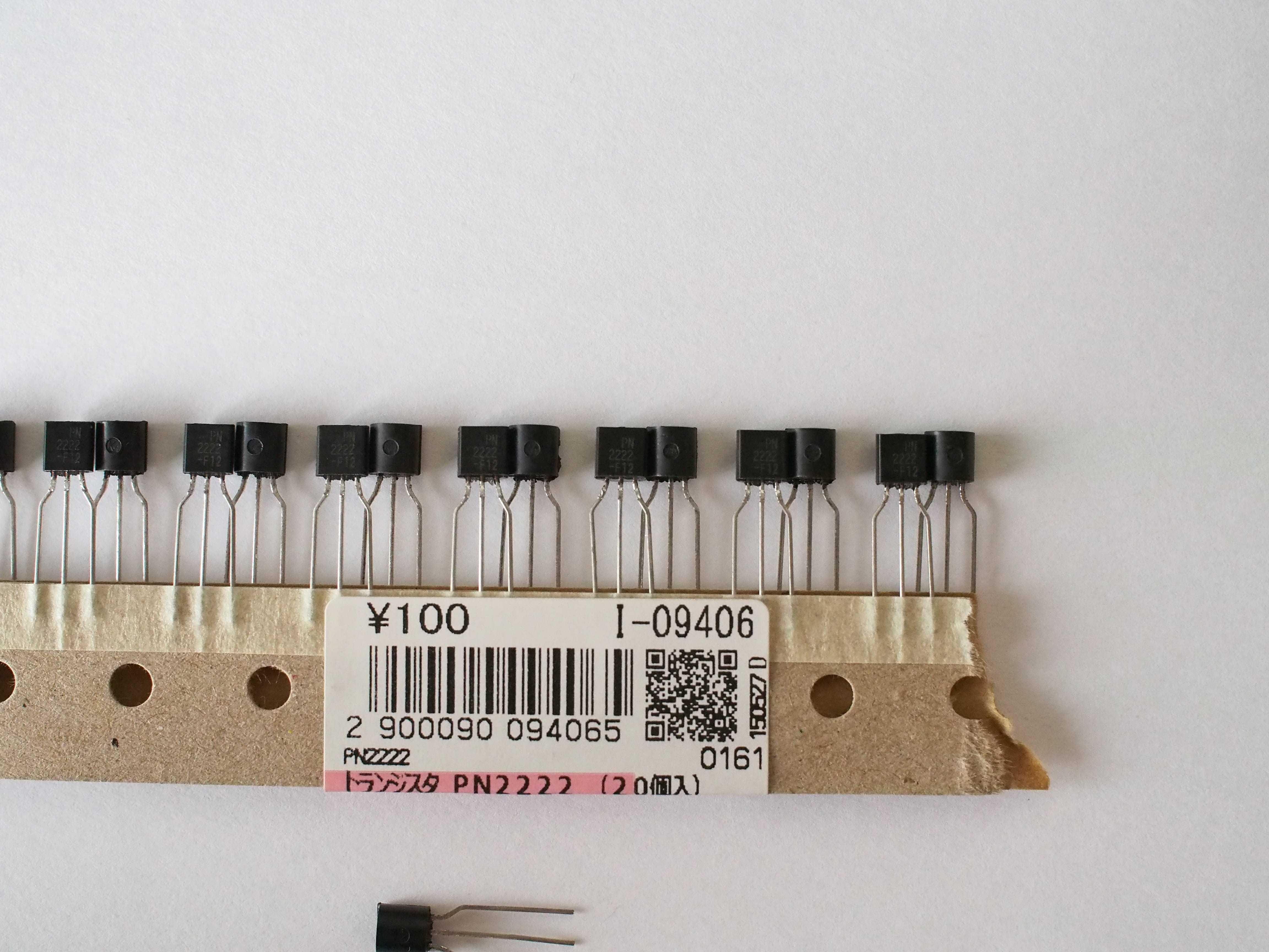
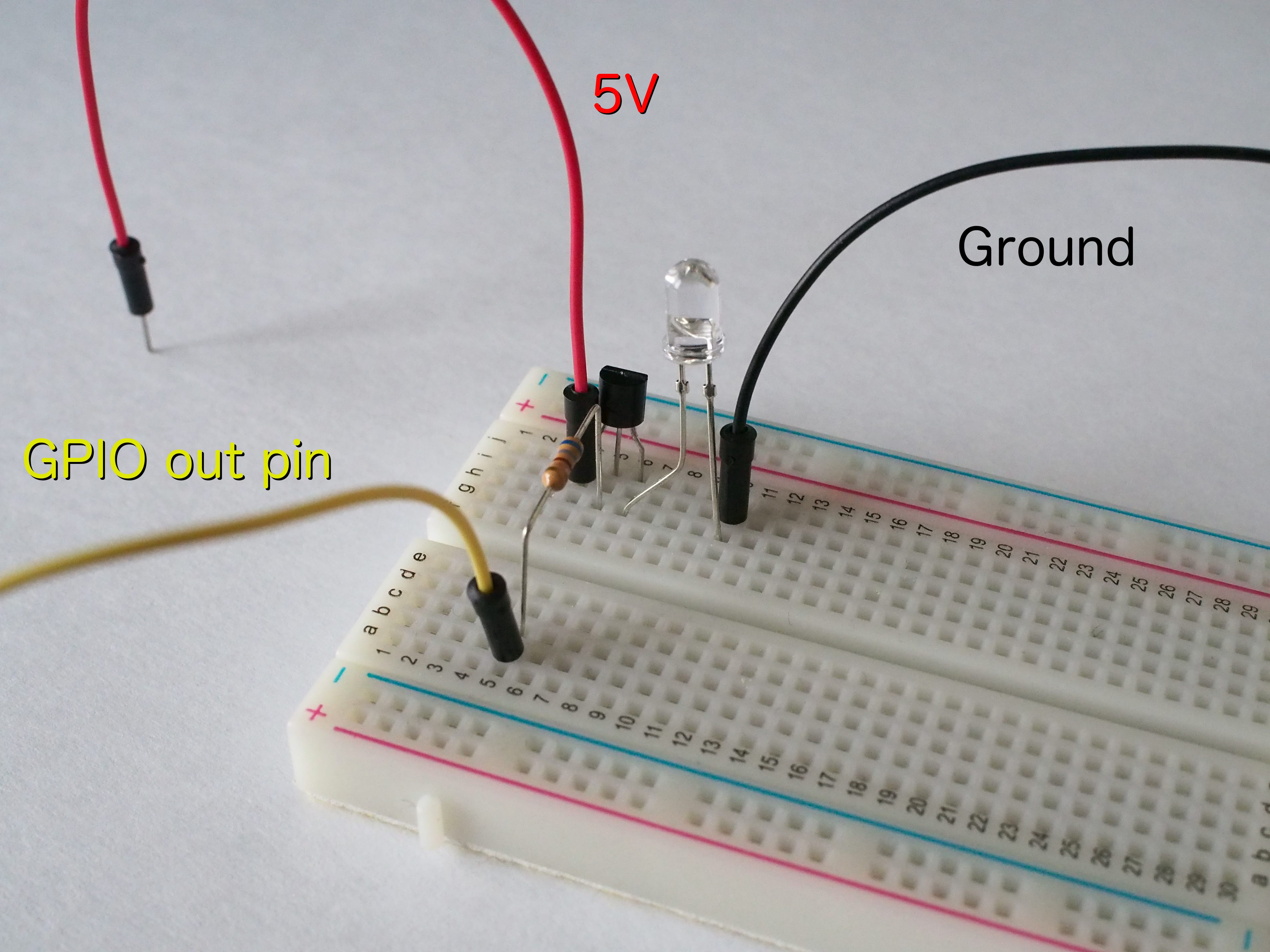
I use a PN2222 [1] transistor to switch a 5V supply through an infrared LED from a microcontroller. It works, but should I be using something better/smaller/more cost effective/more appropriate for the circuit [2]?
No, in fact in that circuit the PN2222 is the only thing limiting current to your LED. If you switch that to a MOSFET you'll blow up your LED unless you add a series resistor. (are you sure you aren't already giving too much current to your LED?)
I think the author describes my point of view and defuses many of his own points at the very bottom of the page:
    also, you are likely making one circuit, not planning
    on mass-producing 1,000,000,000 of whatever it is; who
    cares if you spend a buck where a dime might do? you
    want it to work first time every time, right? this is
    art not technology (eg. industrial capitalism); we
    have different design criteria here.
That's exactly right. I'm usually making one circuit, and not mass-producing them. My inefficiencies will likely be limited in scale to no more than cents per month on the electricity bill. If I were mass-producing, then of course I'll reach for the low-power switching FETs.
IGBTs, although very expensive, are also interesting alternatives to MOSFETs and relays where large voltages need to be switched where speed isn't critical.
Yes, but even so, they also have half bridge chips, all the biasing and compensation, the correct diodes etc. The point is, a motor controller chip is more modern way that the old transistor or MOSFET way. unless you are designing some cheapo thing that will be produced in the millions and have to scrape every penny out of the design, it is better and easier to simply use a motor controller chip in my view.
Maybe you have a box full of transistors and diodes in the closet, because they're kinda needed for everything or at least very useful to have around. You can start building yesterday.
If you want that special bridge chip, you start looking through online stores and datasheets (what a chore, why do they have to suck so hard?), trying to find the chip that has the availability, a reasonable price, the right specs and appropriate package for your use. Then you pay the shipping cost on top of the component, which might be more than the component itself. Then you wait a week or two for the thing to arrive. Then you pray it is intact and you can maybe start building. Hope you ordered the right part and didn't make a mistake in reading the specs.
Why use a 120 in todays modern age? Because that thing you're repairing was Woz'd to the point that that VCE plays an important part in the circuit's operation.
Keep your TIPS, you might not necessarily use them for that brand new design of yours, but you'll probably use them for something.
Now if only we can get people to stop antique computer languages from 1972. (yeah, yeah, I know, special cases. In fact I'm current working on a project using C on three different microcontrollers).
I like FETs as much as the next engineer but if you're going to write about them, try to not make things worse.
In particular, this made me sad: the 10K resistor to ground isn't strictly necessary, but it ensures that the MOSFET remains OFF if the arduino is disconnected or it's pin is not an OUTPUT.
I was helping a high school student with a transistor project and he was complaining that "half the FETs he bought were 'bad'". And they weren't really bad, but they were destroyed. They were destroyed because, like our author, the student had no understanding of how the FET worked and so didn't realize that when you exceed the maximum Gate voltage on a FET it generally causes a current to "jump the gap" to the source and that permanently breaks it. What is even more, since the gate is essentially a capacitor, you can just touch the gate with your finger and pass enough charge (without feeling a shock or anything) to greatly exceed the gate voltage. Pick up the FET without being grounded and "boom!" dead FET.
Now there is almost no way to generate enough current by touching a Bipolar transistor to kill it, and so they continue to work for a long time while plugging them in and out of breadboards.
Do they dissipate more power? Absolutely. Are they difficult to run in parallel? Sure. But they are pretty robust parts. Sort of like the difference between alkaline batteries and LiON rechargeable batteries. Sure the latter are a "better" choice, you can recharge them after all, but if you use them wrong they catch on fire, if you short an alkaline battery it gets hot but doesn't go ballistic on you.
So those "antique" parts are generally very cost effective, very robust, and easy to get. So they make excellent tools to teach you the basics. Do you want to stay with them as you get more advanced? Probably not, but you're probably not skiing on the same skis you learned on either.
/endrant