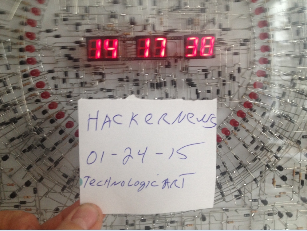
Having built small discrete projects myself, the effort that has gone into linking all those parts without a board and ensuring that there are no touching wires makes my head hurt.
What blows my mind is not even wiring this up - it's how he managed to debug this when he made a mistake (say, plugged something backwards or let the wires touch). On a project of this size and scale it is pretty much impossible not to make one at some point, no matter how careful you are.
Without knowing his process, I wonder if he doesn't possibly use clear nail polish or some other paint-on / spray-on coating as he goes, to prevent leads from shorting out.
That part seems reasonably clear; an oscillator is a very simple circuit, most of the work is just going to be hooking it up to the displays correctly. You can design a circuit like this in a software simulator, put it together on a breadboard. Not saying that's what happened, but it doesn't seem like the hard part.
I felt like such a badass plugging in a LED to an Arduino and making it blink. This is a powerful piece of art to me because it is so complex and beautiful at the same time.
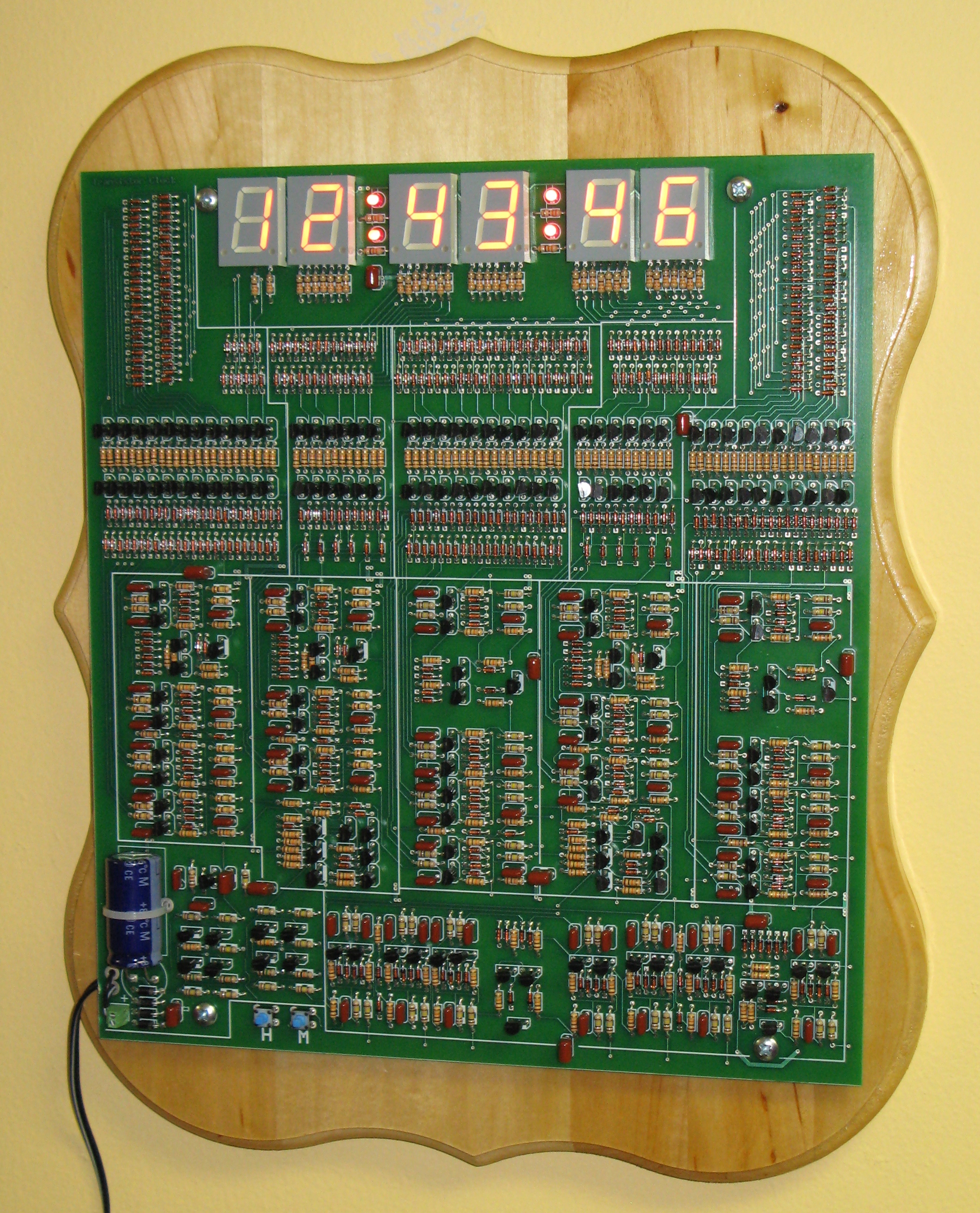
The amazing and artistic thing about this is not the circuitry itself - it's just a series of dividing counters and a shift register (to drive the seconds ring) - but the layout. The images are also right at the edge of being high-resolution enough to tempt me to reverse-engineer a schematic...
I concur. The emotions the imagery invoked in me was a rare experience, technology hasn't invoked such feelings for years. So not sure if it is feeling associated with art, but still, it made me happy, and I do acknowledge the work as art.
Because if it did, then at least in the US, the 60Hz grid frequency is no longer a 'good' stable time-of-day clock reference.
Anecdotal evidence (my own old 60Hz line-synced alarm clock) prior to this experiment kept very good time (drift of 1-2 minutes over a year or more). Ever since this announcement, it has drifted fast such that I need to reset it about once a month for it to be reasonably accurate. And the drift now after a month or two is on the order of 5+ minutes.
The signal can still be pulled from the output side of a simple wall-wart type power adapter. Here's a Maxim app note that describes how you might do that:
This is about how the UK National Grid manage power availability at peak times. Over here we're running 50Hz rather than 60, but one of the key goals is to keep the grid frequency as close to 50Hz as possible.
At around 2m15s into the clip they lose power from a French on-demand provider and the frequency takes a "nose-dive" to 49.6Hz causing the operator to call on backup from a Welsh hydro-station to keep up with demand.
Theoretically in the UK we should get 4,320,000 cycles per day, but I suspect it's probably + or - 3 cycles. Unless of course it eventually balances out over the course of several days.
    Page P1-29, Definition D-D1, Tolerated Range of Discrepancy

    A discrepancy between SYNCHRONOUS TIME and UTC is tolerated
    within a range of ±20 seconds (without need for time control
    actions).
And corrective action is to change the global-grid setpoint for frequency (of 50Hz) up or down by 0,01 Hz (i.e. 1sec difference in time shown on a clock / 5000 seconds of real time). So the system allows for ±20s·50Hz=1000 cycles of deviation until corrective action starts, and allowing for some time until the system reacts, that means that the clock might be off by ±30s in reality (the last one is a guess by me).
But it's part of a much more elaborate scheme with several control-loops taking care of different things, the timing is only the global, outermost, regulation. All this makes much more sense, once one has realized that phase between two parts in the grid is the main controlled variable to determine flow of energy, so this document may appear to be quite obscure and strange to most people.
I always wondered what the importance of maintaining such an accurate frequency is. Are there reasons other than keeping parts of the system in phase? (From what you're saying it sounds like they take additional measures to ensure that too.)
I agree with you that "always accurate" is an optimistic statement but I wouldn't say any level of accuracy from that note is implied. A well engineered solution would take the 5million figure as an average over a longer period of time as stated.
When I first discovered that this was how grid demand was managed, stood in a UK National Grid control centre next to my brother who was interning for them, I was amazed.
Yes, I was under the impression this would be automated. I'm sure many parts of demand management probably is, but the manual intervention involved to keep things under control during simultaneous mass tea breaks surprised me hugely.
I suspect he uses both 120VAC and 12VDC - the first to provide a clock reference, and the second to power the circuitry. It wouldn't be hard to wire in the 120VAC connection in addition to having a 12VDC adapter.
The C64 did this (pretty much). It had a rarely used realtime clock function in the CIA 6526 (Complex Interface Adapter) chips. You could power the C64 off just 5VDC for most purposes (or a voltage roughly in that region - I experimented with running mine off both a 4.5V and 9V batteries; it was surprisely robust against abuse from people like me who preferred physical experimentation to actually reading up on what'd be advisable to subject it to), but if you didn't provide an AC source on the right pin too, the realtime clock and the user port wouldn't work as they should.
Theres a transformer 120 vac to 12 vac and i use the signal of the 12 vac. Theres 3 wires that goes from the power supply unit to the clock, Ground, +12 DC and the 12 vac 60hz signal.
Use a diode so you only get half of the sin waves, that's 60hz which makes it very easy to build a clock off since you don't need to do any multiplications on the base clock frequency it self.
True ... not so good for efficiency and you'd need a bigger smoothing capacitor. (I'm assuming since this is all discrete, there's no need for a fully regulated power supply).
You'd want a fully regulated power supply for this, /especially/ because it's discrete. You want the LEDs to remain constant brightness, but, more importantly, you don't want an unregulated power supply to overvolt and destroy all this hard work.
Years ago I created something in this style (well, sort of: contained no actual logic, just lit leds and stored a small amount of energy so it took minutes to fade them out, and doesn't even come close to the achievements of this guy) as a gift and I was quite proud of it: http://i.imgur.com/vYs619y.jpg
Very inspiring ... I spent 20 years as an embedded systems engineering before switching solely to software. I've done a few contract projects but this makes me yearn for something that's simply artistic. Any ideas?
Does anyone have any recommendations of basic circuit emulation software that could be used to tinker with ideas like this without destroying actual hardware?
In the UK schools used to have software called 'crocodile clips' which could show things like the current flowing through each junction, but it's too basic for larger projects like this.
You are getting modded down, but you are correct his description has a few sentences that are bad enough to be somewhat off-putting. Its bad form in the art world to call something you created a masterpiece or extraordinary (even if it is).
I chalk this up to lack of experience.
The work is beautiful, it would be better to have less hyperbole in the description .
But, the thought of soldering all of those junctions together; what is the process for testing something like this as you build it? What if you make a mistake and don't catch it in time? Like you hook up a diode backwards...
The artist probably built it in segments which they could test individually then assembled it together, probably testing sub assemblies too. It'd be crazy to try to build this all at once. And since most of this boils down to a series of pulse dividers it's relatively simple to test them in pieces.
I think it's more likely the design is modular - build your BCD counter out of smaller modules, breaking it down to gates. You can repeat the 3D design of each functional unit.
Still awesome though. Especially that central ring, which is just there for the look of the thing.
I'd be a little worried there are no decoupling caps anywhere, so it could be a touch glitchy - although at 12V you'd have good natural noise immunity, so I guess that's not a problem in practice.
"Since glass covers the complete artwork, there was no way adjust the time using buttons which was simply solved by hovering an elegant handcrafted piece of magnet over specific locations over the glass frame. Electro- magnetic micro switches inside the frame responds to the magnet and adjust the time. The "Time adjusting magnet" has a chrome handle tip and its magnet side is covered with velvet."
This is beautiful. I hope he posts videos. It reminds me of the old electronics of my childhood; radios and TV sets that had point-to-point wiring on terminal strips. No circuit boards! But they were never this beautiful.
Having been an electronics hobbyist myself I have great awe for his projects. Are there examples of software that are analogous to
'the clock' in their power to inspire awe?
The dual digit displays are probably simply encased LEDs but it would be nice if there was a way to expose the inside of those too. Aesthetically they seem out of place.