Usagi Electric has a video series[1] about investigating MC14500B (with help from Ken) and recreating it on a bread board. Later this led to him developing a variation on MC14500B using vacuum tubes[2].
I really would love to do a project like that, but I'm already trying to justify my "build retro computer using 20 yr old components that are now dirt cheap and a 35-40 yr old CPU projects" - e.g. 68010 and 286 and friends.
I'm way too young to have had the opportunity to experience these machines first hand let alone have any attachment to useful software that may have ran on them. Retro-computing has been a way for me to experience some of computing's past.
>The MC14500B has an unusual architecture, making it more of a building block than a complete microprocessor. [... It] requires multiple external chips to make it usable.
Love the articles you've been posting, Ken! And yes the MC14500 requires multiple external chips to make it usable. In fact, HNers may recall the one-bit machine whose chip-count I optimized by eliminating the MC14500B itself!
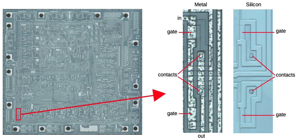
Can you help me understand the relationship between the metal layer, the vias, the gate, in and out? The middle image in the above link makes them seem like they are all connected. Does "in" provide the voltage the that pulls a gate high and turns it on or off? Are the vias and contacts just used to provide connection to a power rail?
Also what governs the fascinating shapes that we find in the two gate outlines such as in the image link above? They looks like and L or P outline. How do they arrive at these? Is it a just a function of floor plan routing and satisfying some minimal surface area needed?
The metal wire connects the input to the two gates. The PMOS (upper) transistor turns on if the input is low; it connects the output (right) to the high voltage (left). The NMOS (lower) transistor turns on if the input is high; it connects the output to the low voltage. Each transistor has a contact (via) that connects the transistor to the gate's output. Thus, working together the two transistors implement an inverter. The power connections to the transistor aren't shown in the diagram; they are off to the left.
As for the shapes, they are basically created as a consequence of the routing. The gate is the important part; it needs to be a rectangle with specific dimensions (based on the circuit). The rest of the transistor can meander as needed. Because there's only one metal layer, a lot of routing needs to be done through the silicon.
The cross-section diagrams earlier in the article might help.
>"The power connections to the transistor aren't shown in the diagram; they are off to the left."
What does the power connection to the transistors look like? I guess it's another two vias, one into the source side and one into the drain side that connect to the power rail? I'm guessing there's metal in the source and drain similar to the gate where these terminate?
>"The gate is the important part; it needs to be a rectangle with specific dimensions (based on the circuit)."
Could you elaborate on why it needs to be rectangle? Are the specific dimension based on resistance needed in the circuit then?
> What does the power connection to the transistors look like?
With one layer of metal, power wiring is tricky. You need to get power and ground to all parts of the chip in the metal layer, without crossing. (You can use the silicon layer to cross if necessary, but this adds resistance so is avoided if possible.) So you end up with power wiring either meandering all over the chip, or an interdigitated tree-like structure for power and ground.
A via connects the power (or ground) metal wiring to the silicon layer. This silicon will often feed several nearby transistors, rather than one via per transistor.
(Hopefully this makes sense.)
> Could you elaborate on why it needs to be rectangle?
I guess you could have non-rectangular gates, but it's not something I see. The gate is where a metal line crosses a silicon region, so you naturally end up with a rectangle. The current is proportional to the width::length ratio of the gate, so the dimensions are important. (And one dimension is normally constrained by the minimum feature size.)
>"A via connects the power (or ground) metal wiring to the silicon layer."
Would those vias be what's labeled here in this diagram as "metal contact" above both the source and drain then? Is it just for simplicity sake that they show it having a one to one relationship?
Yes. (I can never remember the official difference between contacts and vias, so I use them interchangeably.) However, an important thing on a chip is that you don't need to connect the source and/or drain to the metal layer; you can connect it to something else through the silicon. You can extend the source or drain (i.e. diffused silicon) until it runs into another transistor's source or drain. There's not really any difference between silicon doped for a source/drain and silicon doped for wiring. This is especially useful when you have a single layer of metal wiring, since you can cross signals by using metal wiring for one and silicon wiring for the other.
I was browsing on the processor architectures on Wikipedia and caught my eye on 1-bit processors. I decided to read more upon that, and found your article and found it interesting.
Because it is more interesting than the use of ML in Bitcoin trading, for example, thanks for sharing it. ;)
I don't know if you are still here answering questions, but I was wondering "What if we sent a musical signal (digital or analog) through the MC14500B (silicon junction or vacuum)?" Could it be used, say, in a programmable guitar effects pedal?
The chip doesn't really have the performance for audio processing. It operates at 1 MHz, but since it operates on one bit at a time, you'd probably only be able to perform a couple of additions on each audio sample. So not really enough for effects.
Thanks, that makes sense--maybe operate 16 in parallel? Logic (human) still probably wouldn't stop me from trying if I had one laying around--what the chip would do outside of the design discipline, that is. :)
These are both one-bit processors, but very different. The Connection Machine had a 1-bit ALU and it operated on larger words serially, so to the user it looked like it was doing 32-bit arithmetic (or whatever). The big deal about the Connection Machine is that it had 64K processors operating in parallel, so it formed a massively-parallel supercomputer.
The Motorola chip on the other hand was "genuinely" one bit. It was designed for Boolean control applications with one bit values. (You could do serial arithmetic if necessary, but it was very inconvenient.)
I have programmed once, many years ago, when I had just finished my studies, such an one-bit processor, and I will describe the application, because I suppose that most people now are not familiar with what can such a processor be useful for.
That one-bit processor was not made with a Motorola 14500, but it was implemented with a board with TTL integrated circuits, but its architecture was very similar to the Motorola one-bit processor. Actually it was rather the other way around, such programmable one-bit processors made with bipolar ICs had been widespread in the industry before the appearance of microprocessors, and Motorola has attempted to substitute them with a CMOS circuit with higher scale of integration and lower power consumption.
That application on which I have worked was in a metallurgical plant where various metal forming processes were done, e.g. metal sheet rolling or metal bar extrusion.
Such a huge installation for metal working had many multi-megawatt DC electric motors, whose variable speed and torque were controlled by thyristor converters and hundreds of movable pieces, which were moved hydraulically, so the movements were controlled by opening or closing hydraulic valves. There were also many sensors, some continuous, e.g. measuring the speed of the electric motors, and others discrete.
The control unit for the metal working installation was implemented with the logical one-bit processor, together with an analog computer made with operational amplifiers.
The analog computer controlled the speed and torque of all electric motors, and all analog sensors were among its inputs.
The one-bit processor controlled all on-off devices, i.e. all hydraulic valves and all electromagnetic relays (which enabled the supplies of the hydraulic pumps, of the fans and of the high-power DC electric motors).
So the one-bit processor had around one or two hundreds of one-bit logical output variables and a similar number of one-bit logical input variables, all connected by complicated Boolean equations.
For both the logical one-bit processor and the analog computer, the inputs and outputs included not only the connections to the metal working installation, but also the keys and joysticks and display devices of the control panel used by the operator of the installation.
After cheap microprocessors became available, and also cheaper DACs and ADCs, a single-board computer could be used to do what previously required an entire cabinet with a logical one-bit processor and an analog computer.
I'm trying to imagine how a system which includes this processor should look like, and how it should be designed. A detailed example, even a simple one, would probably add significantly to the understanding.
Well, that's probably why the chip wasn't super-popular :-) The chip reduces your part count somewhat -- it would take a bunch of TTL chips to replace it -- but it's not like a microcontroller that solves your problem entirely.
I've always thought it would be a historically interesting 'what if...?' to try to build an entirely mechanical version of something like this controlled by a jacquard-style card-reader mechanism.
Microcontrollers started (oversimplifying a bit) with calculator-based chips: the Intel 4004 (1971), TMS 0100 (1971), TMS 1000 (1974). The Motorola one-bit processor is from 1976, so it's a later chip, more of a strange branch than a precursor.
[1] https://www.youtube.com/watch?v=oPA8dHtf_6M&list=PLnw98JPyOb...
[2] https://www.youtube.com/watch?v=y149hLe1zYo&list=PLnw98JPyOb...