> Logging filesystem are beautifully elegant. With a checksum, we can easily detect power-loss and fall back to the previous state by ignoring failed appends.
An edge case when designing a log-structured file system is that a corrupt checksum in a log entry could actually mean one of three things: power loss while writing the last transaction, a misdirected write or bitrot, or a misdirected read.
If you simply read the log up until the corrupt checksum, assuming this can only mean one thing, then you might fall too far back and lose data that has been acknowledged to the user as synced. This could in turn then break the guarantees required for implementing things like Paxos, which could ultimately wreak havoc with a distributed system.
To detect power-loss, you need more than just a checksum. You need a checksum, but you also need a way to "snap" the new log tail onto the old log tail in a two-phase commit. So you write out all your data, then you write out your new log tail, then you sync, then you snap your new log tail on using two atomic sector writes, one of which needs to be synced.
The number of syncs are the same as before, you haven't actually added any additional syncs, but this way you ensure that your log references data which exists, and you can now tell the difference between a power failure and a corrupt log entry.
A power failure is recoverable (roll back), but a corrupt log entry is unrecoverable (assuming no log entry replicas) and means the file system is unmountable.
I'm not sure I'm following this snap operation. What is a "log tail" in this context? Does this the snap operation still work if we are copying over entries of the log lazily and we don't have a definite end-of-log?
You are right though, a checksum used this way provides no protection over bit errors or misdirected write/reads. But, if you assume no bit errors, a checksum can provide power-loss protection as long as there's a fallback.
But doesn't this just move the problem somewhere else? Yes. In this case it moves error detection onto the block device. But it turns out performing error detection/correction at the block device level is simpler and more effective. Most NAND flash components even have built-in ECC hardware for this specific purpose.
This is not my field of expertise, so forgive me if im mistaken, but isnt 'Ohad Rodeh B-trees'[1] a simple and more elegant solution than a journal/WAL?
As far as i know its already used in Linux Btrfs and in LMDB, and i wonder why, if they were designing this from scratch, why they didnt go for this in the first place. Familiarity perhaps?
By the way i have code that deals with the SQLite Btree directly and by reading your comment now i understand why theres a need for a two-phase commit as expressed in:
"Usually, microcontroller code is simple and reactive, with no concept of a shutdown routine."
Really? Nobody uses brownout interrupts to lock down on power loss? I almost always do a few things as the power is fading, flagging the situation at the very least in order to clean up when power is restored.
Really. It's best not to trust on shutdown procedures for fail-safe persistence if that really is important. Use log-structured file-system and do cleanup and verification when the power is restored. When microcontrollers have brownouts, it's best to assume that you may have already garbage in the memory bus.
Of course, when improved fail-safety exist just to improve reliability measured in hours and fail-safety is not critical function, all what I said is irrelevant.
Brownout detection isn't sufficient. There are many other sources of "instant stop", from simple hard-crash bugs to bit-flips in RAM that either cause a crash or multiple-bit ECC fault, take your pick because they will all turn out the lights without warning.
For consumer devices there's ESD testing, where devices are subjected to several kilovolts of zap in certification tests and are required to survive. Typically this means the device will reset and recover, but it needs to be in usable condition afterwards. If a surprise reset results in a toasted file system and a brick, you won't be able to sell the device in markets that require this testing, which is most of Europe and (I think) the US.
The right way to do a persistent store is to expect the lights to go out on any arbitrary bus cycle and design around that.
My understanding was if the function is interrupted on discharge, you fail the test. At least that's how our equipment was tested by an independent lab.
Might be different depending on the market. For us it was "we can reset, but we have to recover within a few seconds". I never questioned the wisdom of our hardware cert engineers.
(My experience at three different companies spread over 35 years was, if you were a software engineer helping the hardware types with ESD or RFI testing in the lab, you were definitely going to get zapped at some point. That made you part of the team, though ... :-) )
As it was put to me, if a discharge leaks through, there's really good chance that another, or 3rd, or 5th would be fatal: the device is not adequately protected. But probably that's not a big deal in some applications.
My usual design is to monitor AC powerline with opto-coupler and then enter the brownout procedure in MCU when the power loss is detected. The remaining energy stored in AC/DC converter capacitors are then used for a graceful shutdown purposes.
The usual brownout procedure actions are: a) flush the current state to MCU flash memory (EEPROM) so that the work can be automatically resumed; b) wait for a power-on condition.
In this way, the device is able to significantly reduce flash memory wearing. It turns to be a significant winning factor in cheaper MCUs, as they only allow about 100,000 EEPROM write cycles max.
And it comes for cheap, as the only thing you need is an opto-coupler plus a bit of software wizardry.
Nope. Because brown-out detectors on micros are meant for momentary glitches and unreliable. The detectors can preserve a brown out detected bit in their reset cause registers. However, they don't guarantee the micro's core will get the interrupt in time before losing power. And if the brown-out goes down to POR levels, you won't even get the brown out cause bit and instead POR.
The best you can do for file systems is track a "dirty flag". You keep it set unless you power down willingly yourself.
You design the circuit... You can decide exactly how many microseconds of power you'll get between the brownout interrupt occurring and the lowest operating voltage. Your job as designer is to write the code to guarantee completion in that time.
Microcontrollers don't have to suffer the same issues as app/web developers. They can know exactly how many clock cycles something will take.
(a) you don't choose how long you get because the uC manufacturer already chose. (An external brownout warning is different, and useful, but still not a good solution to the problem of FS integrity.)
(b) those thresholds have nothing to do with the operating thresholds of the flash (which usually require a lot more energy to do work than the uC)
(c) writing to flash is a relatively high-power operation, and if you need to erase, you're doing the highest-power operation at a time when you have no power buffer
(d) warmup time to do an erase is measured in milliseconds, and you probably don't have that much power buffer
The best you can do at brownout is minimize the damage, because your uC is about to switch off and/or silently inject errors.
I don't personally usually bother, but an EE approach would be to put a diode between the 3.3V supply and the MCU/flash power supply pins with a large bulk capacitor, and use the voltage just before the diode as your brownout detection. It can't discharge back into the power supply or other parts on the board because of the diode so the capacitor just needs to store enough charge to run for a specified time after power loss.
Then you can configure how long the MCU runs after power shuts down. Put 470uF there and I imagine you'd have your milliseconds easily.
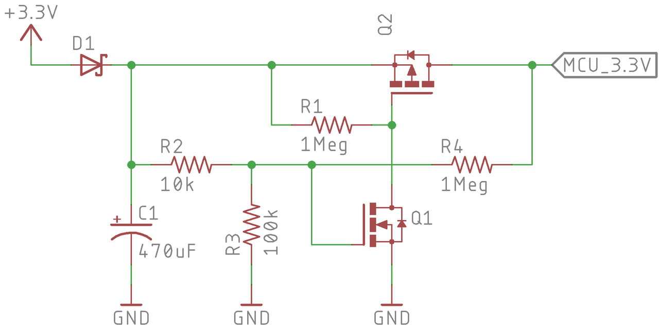
Another reply mentioned that many MCUs don't like it when power is applied too slowly. Here is a version I just made as an example that uses two MOSFETs and a resistor divider to delay application of power to the MCU and flash memory. It relies on the N-channel MOSFET turn on voltage along with the resistor divider to set the turn on voltage, and when it reaches the threshold the P-channel MOSFET turns on.
Note the resistor R4 provides hysteresis -- after the P-channel MOSFET activates it acts to keep the N-channel MOSFET active unless the voltage drops below some level set by R2, R3, R4, and the turn on voltage of Q1. You just need to tune them appropriate for your components, and granted of course it adds some amount a bit to your BOM cost. But if you need it you need it.
So basically, R2/R3/Q1 set your turn on voltage (experimentally determined or maybe with Spice) and R4 sets your turn off voltage with R2/R3/Q1. The MCU probably uses under 500mA so these parts are pretty cheap... the capacitor is about 5 cents (https://www.digikey.com/product-detail/en/kemet/ESK477M6R3AE...) and the MOSFETs that looks appropriate are in the 6 cent each range.
Most mcus are fine with power being applied slowly as long as they have a separate reset signal. It's good practice to have a separate reset signal anyway, to avoid unintended behaviour while the circuit is powering up.
You are still asking for trouble. Once something goes into latchup, reset is unlikely to recover. If not the MCU, then some peripheral on the same supply may express it's dislike for intermediate voltages.
But you can just... Decide how many clock cycles you'll need to finish shutdown, calculate that power usage, then solder a corresponding power source in place. There really isn't guesswork.
Flash over SPI isn't very predictable. There's a boatload of internal state -- they silently do R/M/W, there's internal stepup converters with unknown voltage levels, temperature variation greatly impacts write time, and, depending on your software stack, you might need to do an erase.
Assuming you only need to execute one Flash transaction (doubtful!), covering all of the variation might take upwards of 50ms.
So, yeah, you could just throw a massive cap on the power rail. Except that that conflicts with the other power, cost and size constraints implicit in the context of microcontroller systems.
In one project I worked on we monitored the 24V rail and when it was dropping, the MCU had enough time to do cleanup /shutdown work until the 3.3V supply dropped.
anything with a 24v rail has much more power budget/bulk capacitance than most small embedded devices... so what worked there may not work well in other more common cases
Many MCUs do not appreciate slow rise-times when using their internal regulators. Then you start oversizing your regulator or providing them replacement regulators. Which then opens more cans of worms, etc, etc.
And if you don't have this, I posted this circuit example I just made for a delayed power turn on time above. Capacitor is about 5 cents, the transistors are about 6 cents each. If you need it you need it, but power good to the reset line is better.
Those microcontrollers aren't reliable anyways. If you design those in you have to accept that if they have persistent state they will eventually brick themselves. If they don't have persistent state they will hang and require user intervention on a regular basis.
Yeah, paying thirty cents for a capacitor to coddle a ten-cent MCU doesn't make a bunch of sense. Much cheaper to teach your software folks how to write transactional updates to that flash. Typically you pay a small speed penalty to get update atomicity (in addition to having a more complicated implementation).
Wow, this is pretty cool to read. I'm in college for CS right now and this uses most of the stuff I've learned so far. It's neat to see all of it come together.
Afaict checksums only cover metadata and it doesn't do any read integrity checking, isn't that bad when talking to raw flash devices since it relies on them accurately reporting errors?
Microcontrollers almost always use NOR flash, which is much less error prone than the NAND flash in your ssd.
Still, if you need ECC (maybe it's a medical application), the company designing the MCU would build it directly in to the embedded flash. The foundry might have a standard 128-bit word size option, and an extended 144-bit word size option, giving you 16 extra bits per word for whatever ECC or secded code you want to put in. From there, it's on you to build in the right error reporting mechanisms. It's certainly worth checking whether or not littleFS property bubbles errors up if a read operation flags the data as bad.
All this is assuming internal flash, I'm not sure whether external SPI flash offer similar extended word size options. I don't recall seeing any but maybe they are out there.
Error correction provides the same value as a checksum, but better. (the tradeoff is ECC codes are much larger and more expensive to compute)
It's also worth noting the CRC is used for power-loss and doesn't actually provide error detection for metadata-blocks.
Checksumming data is a bit complicated in a file system, mostly because of random file writes. If you write to the middle of a file, you will need to update a CRC, but updating that CRC may require reading quite a bit of additional data to build the CRC back up.
To make random writes efficient, you could slice up the files, but then that raises the question of how large to make the slices. Too large and random file writes are expensive, too small and the overhead of the CRCs gets costly.
You could make these slices configurable, but at this point we've kinda recreated the concept of a block device.
The block device representing the underlying storage already has configuration for this type of geometry: erase size/program size/read size. If we checksum (or ECC) at the block device level we also get the added benefit of also protecting metadata blocks. Most NAND flash components already have hardware ECC for this specific purpose.
TLDR: It's simpler and more effective to checksum at the block device level.
And for MCU development, simpler == less code cost.
> littlefs by itself does not provide ECC. The block nature and relatively large footprint of ECC does not work well with the dynamically sized data of filesystems, correcting errors without RAM is complicated, and ECC fits better with the geometry of block devices.
That is, ECC and read-integrity checking is determined at the block level, not the filesystem level. The filesystem assumes that it's dealing with a block device that either succeeds or reports an error.
There's also some cases where you don't care about the devices that develop errors.
Wear-leveling delays wear errors until the end of the device's life. Once these start to develop you will eventually have storage that's unusable. The cheapest option may be to just let the device crash when it has reached end-of-life.
You could as a sanity check, it would be useful to insure no corrupted data gets passed into your system. Though this wouldn't protect the filesystem completely.
I like the doubled-up metadata records. It is like the mechanism used in transactional exFAT, but covers more of the metadata and is more scalable. At first I worried about the overhead but is is nothing compared to the other overheads in filesystems unless you have a crazy number of files.
I am not sure about the system that generates "random" offsets. It seems that it is based on XOR and linear checksums and I've personally used that kind of method to hash things and had wildly imbalanced bucket use. It's a disaster if you are carving work to thousands of nodes based on the hash but might not be so bad for the intended use.
> and the unfortunate fact is you can't traverse a tree with constant RAM
This is not true. See Knuth, The Art of Computer Programming Vol.1, § 2.3.5).
Generally I wouldn't recommend naive SDW as a good strategy for filesystems, but if you have a fixed number of processes (common in microcontroller applications) it might be worth trying.
Reading through 2.3.5 (Lists and Garbage Collection), it looks like it's describing a tree where the leaf nodes also contain references to the root of the next tree.
This wouldn't work as a copy-on-write tree, as the root node is changed every write.
Copy-on-write behavior requires very strict trees, and this gets in the way of adding extra structures for traversal.
It would be nice for a thing calling itself "fail-safe" to have some amount of formal evidence of its fail-safe properties by way of both checked abstract models & verified source/binary level implementation (I also think the same thing about everything posted here related to security too). I browsed through the repo and didn't see anything other than what amounted to narrowly targeted unit & integration tests.
The test scripts are mostly in Python, so even just some Hypothesis tests (property-based testing framework for Python) would be nice to try to quasi-brute force some more empirical assurance that this filesystem behaves as claimed and expected.
That said, this is likely to come in very handy, and seems definitely worth taking a look at.
All of the flash SSDs I am familiar with have no fixed relationship between a logical block and the actual NAND media backing it. In other words, the device automatically wear levels internally and the only control the user has over wear is the total number of writes they perform.
Given that, I don't understand the discussion of wear leveling in this FS. Maybe someone can explain further.
I assumed so, but then why all the comparisons to file systems that are designed to run on top of a flash translation layer? I would have expected something in big bold letters at the top saying this is designed to run without an FTL, whereas the other filesystems rely on one to wear level. For example, this is right at the top:
"Writing to flash is destructive. If a filesystem repeatedly writes to the same block, eventually that block will wear out. Filesystems that don't take wear into account can easily burn through blocks used to store frequently updated metadata and cause a device's early death."
This isn't true. It's only true for filesystems that aren't running on a regular block storage device. It's even more egregious to use the word block because almost everyone assumes that means a logical block. They must be using it to mean a NAND page, which has entirely different behavior and does wear out.
Honestly most file systems haven't been designed to run on an FTLs (except maybe UBIFS). Most filesystems have been designed to run on magnetic disk drives, where wear is a non-issue and data locality is more important.
As the world transitions to flash, FTLs were created to translate flash in a way that doesn't require rewriting the filesystem. But this adds a layer of abstraction that can make the resulting storage stack more costly than is necessary.
Why the comparison to traditional, magnetic disk based filesystems? Because a lot people are putting them on raw flash and expecting them to work (mostly FAT in the MCU space). It's important to inform their perspective that traditional storage practices don't work on raw flash.
As for everyone assuming block == logical block, I don't think that's true. It's a pretty overused term, in NOR/NAND datasheets it simply describes the physical geometry of the raw flash. Though even there it is inconsistent.
The domain comes with it's own shenanigans, and it's impractical to list all of them. When working with microcontrollers no-one should expect to have FTL.
The word "block" is extremely generic and the semantics and sizes of "blocks" vary widely across different storage technologies, platforms and specific parts.
It's like saying "packet" -- there are a gazillion packet types, sizes and formats, and when I use the word "packet" I don't expect everyone to assume I'm just talking about ethernet framing, even though that's a really popular packet format.
This is meant to run even on low-end micros without need for memory allocation. And support small SPI memory chips where you need to roll your own wear leveling across different size blocks of memory depending on chip vendor.
An edge case when designing a log-structured file system is that a corrupt checksum in a log entry could actually mean one of three things: power loss while writing the last transaction, a misdirected write or bitrot, or a misdirected read.
If you simply read the log up until the corrupt checksum, assuming this can only mean one thing, then you might fall too far back and lose data that has been acknowledged to the user as synced. This could in turn then break the guarantees required for implementing things like Paxos, which could ultimately wreak havoc with a distributed system.
To detect power-loss, you need more than just a checksum. You need a checksum, but you also need a way to "snap" the new log tail onto the old log tail in a two-phase commit. So you write out all your data, then you write out your new log tail, then you sync, then you snap your new log tail on using two atomic sector writes, one of which needs to be synced.
The number of syncs are the same as before, you haven't actually added any additional syncs, but this way you ensure that your log references data which exists, and you can now tell the difference between a power failure and a corrupt log entry.
A power failure is recoverable (roll back), but a corrupt log entry is unrecoverable (assuming no log entry replicas) and means the file system is unmountable.