Fun. If you want PCIe on a SBC without the soldering, I highly recommend perusing Hackerboards. I'm very happy with my RockPi 4 (4GB RAM, PCIe, USB 3, 6 cores), which I discovered through their excellent database.
If I were moving away from the Raspberry Pi 4, I'd definitely consider the Nvidia Jetson Nano. It comes with a massive cooler attached. Pi 4 needs a cooler which will run you around $20. That puts you rather close to the nano in price ($75 vs $100), but the nano also has a GPU that is enormously more powerful and well worth the extra $25. Not needing special HDMI cables (or adapters) for the Nano is another money saver.
The biggest factor though is support. Raspberry Pi has a lot of software support, so you aren't running into weird bugs here and there with nobody around to help. The Jetson community isn't nearly as big, but Nvidia's track record on their software support is generally quite good. In this case, they have an extra interest given their push for commercial applications and that the X1 sees use in the Nintendo Switch and Shield TV (among other things).
M.2 is a connector specification it has nothing to do with speed. M.2 supports applications such as WIFI, USB, SATA, and PCIe. M.2 SSDs are faster and store more data than most mSATA cards. M.2 SSDs support PCIe 3.0, SATA 3.0 and USB 3.0 interfaces, while mSATA only supports SATA. M.2 SATA SSDs have similar performance to mSATA cards, but M.2 PCIe cards are faster. SATA SSDs have a maximum speed of 600 MB per second, while M.2 PCIe cards can hit 4 GB per second.
PCIe support also allows M.2 cards to take advantage of the nonvolatile memory express (NVMe) protocol, which brings a large performance advantage over other types of interfaces due to reduced latency, increased IOPS and lower power consumption.
RockPro64 also has 4x low power A53 cores up to 1.5 GHz and 2x A72 cores up to 2.0 GHz. Big-little style. Just for the curious, so don't need to look it up.
The official heat sink is amazing, and can be used together with a PoE hat. That is a huge winner feature for me since the small fans are obnoxiously loud.
Hack’s creator here - it’s on my list of things to try. GPUs are notoriously hard to get to work on non-intel, having tried to get a few up on Alpha and Itaniums in the past.
VideoBIOS expects to run and expects a well behaving Intel CPU to do the power-up. That said X can sometimes emulate these quite well. On ARM we’d also run into alignment issues and likely other quirks - but in principle...
VBIOS is often not necessary for running a GPU in the OS. The amdgpu driver can POST a GPU by itself just fine.
Still… X86EmulatorPkg allows running an amd64 VBIOS in UEFI on an aarch64 machine :)
AFAIK the bigger problem on embedded boards is half assed Synopsys Designware host controllers. I have a Radeon running on my Marvell MACCHIATObin, on FreeBSD even. But from what I've heard the Rockchip RK3399 has a worse version of the controller, and people trying GPUs on the ROCKPro64 saw errors related to not large enough BAR space or something.
UPD: yeah, someone in the thread mentioned BAR space issues wrt NXP i.MX SoCs, that's probably what's happening on Rockchip. Would be amazing if the Broadcom chip in the Pi turns out to be the one with enough BAR space! :D
In PCI, BAR is Base Address Register, which is a register in the PCI device's configuration space which defines where in the machine's physical memory address space that particular window of memory and/or I/O will be mapped (a single device can have several BARs, for instance a simple graphics card could have one for its control registers and one for the framebuffer). So the "BAR space" would be a shorthand for "the region of the physical memory address space which can be used to map the PCI devices memory through their Base Address Registers". The size of this region is limited, and graphics cards in particular tend to have somewhat large BARs.
(See for yourself in your machine: run "lspci -v", the lines starting with "Memory at ..." or "I/O ports at ..." are the BARs.)
I always wondered what the deal was with Video BIOS on modern PCI-express graphics cards. Obviously it must exist, since int 10h still works.
Does video BIOS even need to be executed, though? I always assumed it was only necessary for the primary card to be able to display output during boot on PCs. (Otherwise, wouldn't two different cards trample over eachother's implementation of int 10h?)
Sorry for the probably-obvious questions, it's sometimes tricky to find good sources for weird information like this that are also up to date.
It’s all, cough, implementation dependent. You can run two VideoBIOS implementations, and chances are only one will install an int10h handler, but both will set up the registers and whatnot in the GPUs.
My AMD TAHITIs for instance need VideoBIOS to start some form of thermal management loop - otherwise they just run full-throttle on the fan.
Then whichever card prevails (BIOS has the ability to select the initialization order) becomes the boot display device.
X11 has some (generally working, for well behaved GPUs) emulation of this environment, so that the GPU can initialize late, and even reset under X control. This is how sane cards can work under headless ARM etc.
Now, some manufacturers assume you get something like SSE or MMX - VideoBIOS spec technically mandates 386 instruction set only.
That crap gets badly emulated.
On top of this, drivers can sometimes reinit anyways, from native kernel code. If that happens, the VideoBIOS concerns are moot.
Thanks for the information. I’ve been really curious about this with the incoming ARM dev boards that have full PCI-e edge connectors.
Pretty fascinating that X11 of all things is dealing with Video BIOS initialization, though. The sheer amount of functionality that was overloaded into X...
Yes — "VBIOS", and these days mostly "UEFI GOP driver", is code that runs on the CPU and allows the system firmware to initialize the card and preset video output before any operating system is booted. Without it, you cannot enter the setup screen graphically, only over a serial port :D
OpenBSD has radeondrm enabled on mips64, powerpc and arm64. It can initialize the board just fine without emulating x86, since KMS. Working 3D acceleration is another story.
OpenBSD even has (or had, build breaks often) packages for chromium browser on arm64 that were tested on this.
People have got at least some cards working on server-class arm setups. On the other hand I think they might be using the 'emulate x86 uefi rom in an arm uefi system' hack, so there might be more effort required on a non-uefi setup. Still, it should have shaken out most of the alignment and memory-cacheability-attibutes issues already, hopefully.
Yep, the "hack" (X86EmulatorPkg) allows running the card in the UEFI out of the box. AMD also provides native aarch64 builds of their UEFI GOP driver though. And none of this is necessary for running the GPU in the OS – amdgpu POSTs the GPU just fine.
> memory-cacheability-attibutes issues
Recently I've added aarch64 support to FreeBSD's port of the DRM/KMS drivers :) Took a couple hours to realize that our implementations of Linux's mapping functions used normal uncacheable memory instead of device memory – fixing that stopped the hangs on driver load and allowed everything to work.
Then there was some corruption on the screen – our drm-kms is from Linux 5.0 for now, and I've had to cherry-pick a fix that only landed in 5.1 I think: https://patchwork.kernel.org/patch/10778815/
Interesting. I've kept my accesses aligned, but noticed that unaligned ones worked. Didn't know about the exception mechanism behind, but yeah, should have err... expected it.
By the way, you can also opt to crash on x86. Just need to enable bit AM (Alignment Mask) bit 18) in CR0 (kernel stuff) and AC (Alignment Check, also bit 18) in EFLAGS.
After that point, unaligned accesses trap. I use this in my CPU JIT/dynamic compiler to trap target unaligned accesses.
"GPUs are notoriously hard to get to work on non-intel"
I don't understand this statement... accelerated graphics have no issues working on any x86 system as well as ARM based linux systems (not to mention every cell phone in the past 10 years). Itanium is also Intel so that statement contradicts your previous statement.
To a limited extent. The accelerated graphics on ARM (and cell phones) has always been a system integrator problem. Until very recently, they were not user customizable - which means the initialisation was part of the proprietary firmware and hard to port across even different implementations of the same SoC.
The x86 world had the advantage of user upgradable GPUs, which necessitates standardization and common firmware.
On top of which, the accelerated graphics of cell phones is a horrible kludge of various standards.
You might run into address space issues. I haven’t checked Broadcom PCIe documentation for RPi4 (is there any?), but I tried a very similar hack with i.MX6 and older AMD and nVidia cards. They get recognized fine, but BARs cannot be mapped because they don’t fit in i.MX6’s tiny 16MB PCIe space.
This would be incredible if gotten to work with a pi. I've been eyeing the Jetson Nano, but if I could use a pi with a V100, that would be hilarious. And awesome.
Based on what I've seen - it's on my list of projects to "try out", but rapidly becoming a more obsolete idea the longer I wait (but then again, I've got an Altair on my todo list, so meh)...
Taking a low-cost Mini ITX board and pairing it with a decent mini-sized GTX 750 TI SC video card (I prefer the EVGA one) should yield a system that is somewhat on par with some of NVidia's embedded ML offerings, with the tradeoff of size and efficiency - but at a significantly reduced cost.
Add a very short PCIe riser ribbon (or, if you can find one tall enough, a right-angle riser), and you could lay the card over "flat" above the CPU (using a 1U cooler/heatsink); you'd have to make a custom mounting frame of course, but I think you could make the whole package relatively compact.
From my limited experience using Tensorflow with the 750 - it is a very capable card in that capacity and relatively inexpensive today. If you were willing to spend a bit more, there are mini-sized NVidia GPUs available in more recent models; of course if space is not an issue, then full-length GPUs can be substituted (my "goal" was to build such a system as close to within the footprint of a Mini-ITX board as possible).
As far as the Mini-ITX motherboard is concerned, again, size to your budget. That said, if you decided to build this system using cheap pre-owned components, maybe an I5 with 8 gig - you could probably get it going for under $250.00 USD, maybe less.
It looks like an unreliable modification. Running a GHz-level interface with jumpers is almost impossible to control the impedance, it's a cool Proof-of-Concept though.
But is it possible to bring the project to the next level? Is it possible to make a daughterboard with QFN connector? If so, one can make a pin-compatible daughterboard with an extension connector. To use it, just desolder the USB chip and solder a new daughterboard on it, and you're ready to go. It would be one of the coolest Raspberry Pi projects!
Yup. The daughterboard is on my mind. Likely flex-PCB and that’s gonna take a week or two to respin. Hence I’m collecting ideas for various daughtercards I could cram in a panel before sending it off - straight-through to riser via USB3, expresscard SMT, maybe through-hole 1x?
That said, PCIe phy’s are extremely robust - they do most of the impedance matching and delay mismatch training. And if you don’t ruin the onboard caps, this could be jumpered straight across.
I was thinking about using a SMT ribbon cable connector because of the limited available space, but apparently it won't be an issue if you raise the board high enough?
Anyway, if this project ever goes to batch-production, make sure to update your blog when the funding campaign starts!
PCIe is surprisingly robust at short lengths. For example, [NanoPi_M4] has two lanes of PCIe coming to the daughterboards via old-school 0.1" connector. Something that many electrical engineers would cringe at, and yet - it works rather reliably.
The Pi4 isn't PCIe Gen 4, though. It's only PCIe Gen 2. Max speed of PCIe Gen 2 is 5GT/s, which equates to the same speed as standard USB3.0/USB3.1 Gen1/whatever its called nowadays.
2.5 GHz, actually. Obviously there's limitations and you have to be careful, but it's not too crazy to think you could use a piece of USB3 cabling to do this. Requires some pretty precise soldering skills though.
We were seeing some issues, one engineer was blaming signal integrity issues, we didn't have access to a high enough speed oscope to get a clean eye diagram, and so another engineer literally disappeared for an hour and had the boards running over the clothes hangars on the old firmware to say, no, it's not a questionable signal integrity issue, go back and fix your code.
Could also look at flat flexible cable like is used to connect Crossfire devices. Those have equal length traces and shouldn't be too far off in impedance.
It'd be nice if there was an easier way to do this (vs. removing a chip!). E.g., maybe a dedicated pinout and an easy way to disable the existing use (since the pins can't be shared).
Now this is the content I come to HN for. A serious hack just days after the 4 was released. Kudos to the OP.
I envy people like OP for their tenacity. I barely have time to follow what's happening in IT, much less get ahead of the pack in doing cools hacks like this.
On the other hand, the fact that the RPi ecosystem remains notoriously proprietary (even the USB controller is a bastard variant that has next to no documentation --- of all the ones available, they had to choose that one) continues to be disappointing.
I definitely like this sort of hack, but such hacks with documentation already available (and doing more than documented, basically) are certainly preferable.
Of course! HN is just a good digest of things on the maker side to the fairly abstract CS stuff to math and physics and all in between. It sure beats the political stuff that becomes tiresome (even though I succumb and engage in it like many posters here).
Aren't PCIe lanes shared? Why would I need to remove the USB 3.0 chip rather than just hooking right to the pins on the device where it's soldered in place?
E: Apparently it's the PCI bus that is shared, not PCI Express lanes. Ty.
Nope. PCIe lanes are not shared. There are some chips (and a lot of motherboards) that allow (or automatically perform) remapping of lanes, though. That's why if you check a motherboard with SLI/Crossfire, it usually has some setting in the BIOS to either dedicate all 16 lanes to 1 PCIe 16x slot or split 2 PCIe 16x slots 8 and 8.
AFAICT lanes are not shared but there are chipsets which can break lanes out into other sets of lanes which are then routed back onto the original set of lanes. So if your CPU has 16 lanes you can hang a chip off of it which then provides more lanes which are then signaled back to the CPU over some subset of those lanes.
It’s not clear if the lanes themselves can be multiplexed with packets from many devices but they can change the number of assigned lanes after initialization so a clever chipset could probably dynamically allocate lanes as used.
motherboard features such as x16 or 2x8 are achieved with "pcie mux" chips. these are devices which select which of N pairs of differential wires is attached to the input/output differential pair. search for "pcie mux" will find many, such as [0]. if you look at the diagram you'll see that it connects wire pair A+/A- to either B+/B- or C+/C- based on the value of the SEL line.
these generally basic passive devices operating at analog signals level, no higher layer activity required. however some may exist which operate as "retimers", which do participate in the lowest layer of the PCIe electrical protocols (generally to extend reach). these are unlikely to be used for a typical x16 <-> 2x8 sort of motherboard feature though.
the example i picked here is 4 lanes, and you would need 4 such chips to do a x16 <-> 2x8. (spoiler: you mux lanes 8-15 from slot X to lanes 0-7 of slot Y, and there are both TX and RX pairs which need muxing.)
there do exist devices called "pcie switches" which operate at all layers of the pcie protocols, and allow for all sorts of sharing of the point-to-point links. examples at microsemi [1] ... for example a 48 lane switch could be used to connect two 16 lane GPUs to a 16 lane slot. this would allow either of the GPUs to burst to the full 16 lanes, or on average if both GPUs are communicating with the host then they would see 8 lanes of bandwidth. there's a picture of such a dual GPU card in this article [2], you can see the PCIe switch ASIC centered in between the two GPUs, above and to the right of the edge connector.
> It’s not clear if the lanes themselves can be multiplexed with packets from many devices
They can be, this is what the chipsets do on most platforms. AMD's X570 splits out 4x gen4 PCI-E lanes into 8x gen4 PCI-E lanes + a bunch of other stuff: https://i.imgur.com/8Aug02l.png
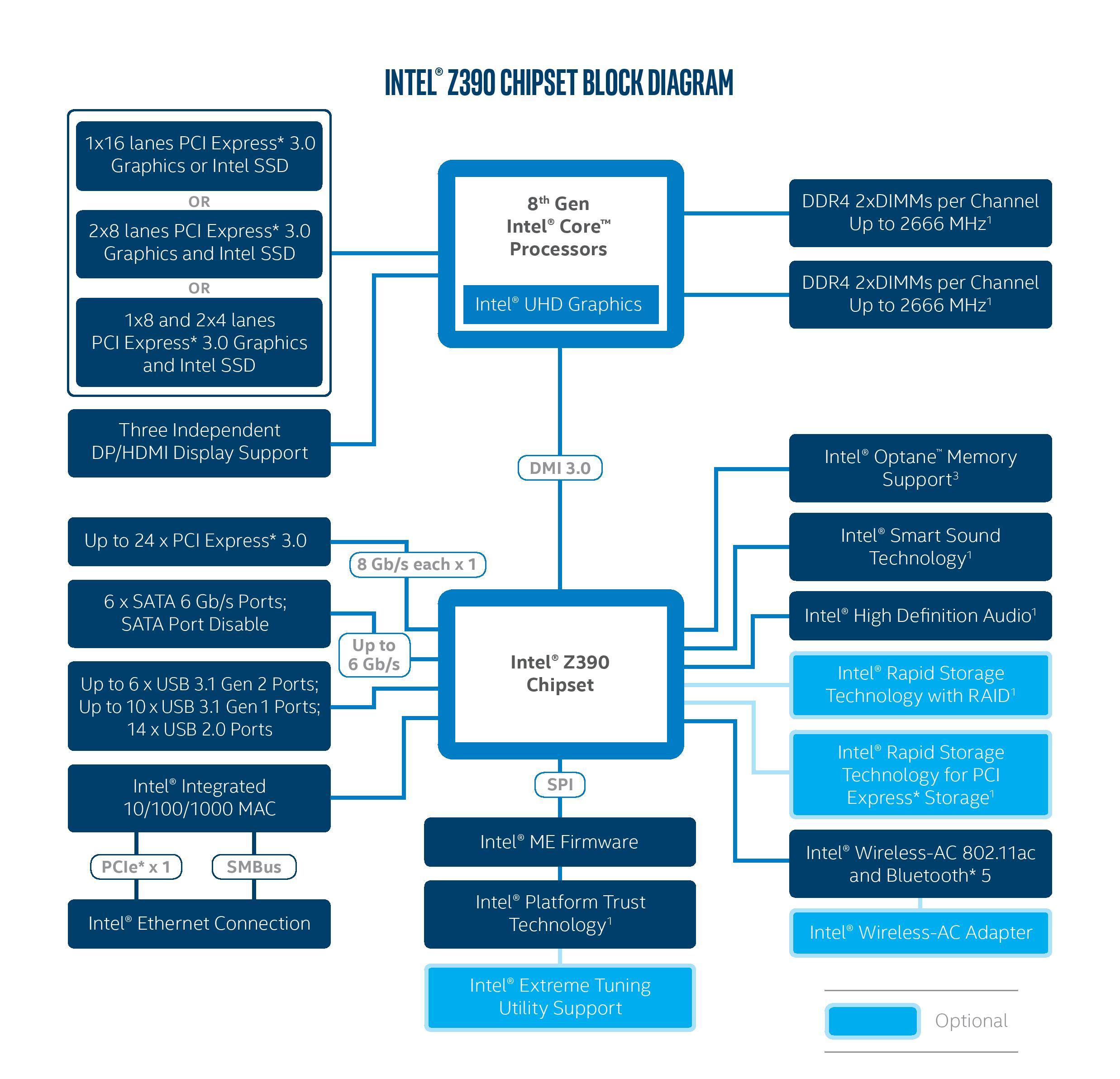
Intel's been doing this better and is what their marketing calls "platform lanes" - the Z390 for example provides 24 PCI-E gen3 lanes from what is essentially a single 4x gen3 uplink to the CPU: https://images.anandtech.com/doci/12750/z390-chipset-product... (DMI 3.0 is essentially PCI-E x4 gen3 in all but name)
If a Pi is capable of this already, why not replace the Ethernet, charging, micro-HDMI, and USB ports with a boatload of type-C Thunderbolt ports (plus support for the HDMI 1.4 alt mode)? Would 8xUSB-C cost that much more than 1xUSB-C+1xEthernet+2xMicro-HDMI+2xUSB3+2xUSB2 (with no PCI Express), in exchange for a considerably more flexible device?
Because there's no where remotely close to enough PCI-E lanes off of the SoC to do that.
Thunderbolt 1/2 requires a pcie gen2 x4 connector to have enough bandwidth. The SoC in the pi4, the Broadcom BCM2711, has just a single gen2 pcie lane. 1/4th the required bandwidth for thunderbolt 1/2, and a mere 1/8th the requirement for thunderbolt 3.
To get a full 8x thunderbolt 3 connectors you need a staggering 32 pcie gen3 lanes off of the CPU. This is out of reach of all but the HEDT & enterprise platforms, to say nothing of the $5 ARM SoC chips for SBCs. Well in theory you could also use something like a Ryzen 3000 and split out the 24 PCI-E gen4 lanes into 48 gen3 lanes and then you could have your 8x thunderbolt 3 connectors, too. But that's expensive, of course.
Thunderbolt 3 controllers have a 4x link to provide one or two ports or 2x in the case of JHL6240. Additionally PCIe is designed to support backwards compatibility and link scaling. I don't see any reason why the 1x gen2 lane of the pi 4 couldn't host a Thunderbolt 3 port; it would just severely bottleneck the bandwidth of tunnelled PCIe links.
Even though it would be limited, a Thunderbolt 3 port would expand the connectivity of the Pi, and very few, if any, devices require the maximum bandwidth to operate at all.
Sure but "hey here's 8x thunderbolt 3 ports just don't ever attempt to use an entire one at once kthx" isn't exactly going to be a great product story, either.
> I don't see any reason why the 1x gen2 lane of the pi 4 couldn't host a Thunderbolt 3 port; it would just severely bottleneck the bandwidth of tunnelled PCIe links.
But that's kind of literally the reason? An entire ecosystem of products assumes a reasonably high amount of bandwidth from the connector. That's its singular reason to exist. If you take away the bandwidth from Thunderbolt 3 it just becomes USB, and at that point why not just offer USB connectors which have even broader support and not as many cabling restrictions?
I agree that 8x Thunderbolt 3 is probably excessive, and I wouldn't want to trade away the current connectivity options as was suggested.
> If you take away the bandwidth from Thunderbolt 3 it just becomes USB
It becomes low bandwidth Thunderbolt / PCIe. You could still use it to attach PCIe devices which don't need a lot of bandwidth. GPUs can be attached for high performance compute where CPU-GPU bandwidth isn't critical. PCIe has non-bandwidth benefits over USB such as DMA and interrupts.
> why not just offer USB connectors which have even broader support and not as many cabling restrictions?
You can't attach PCIe devices via USB, but you can attach USB and PCIe devices via Thunderbolt.
You could also do all that with just a PCI-E x1 slot and use the x1 to remote x16 connector referenced in the blog post to extend it. No reason to mess with Thunderbolt just to have any PCIE capability at all.
A lot of the benefit of the rpi is the built in IO. Would the rpi still be cost effective without it? Not for many of the IoT projects that make the rpi so popular.
I didn't propose replacing the GPIO, or the camera port, or the other display port. I'm talking specifically about the other ports around the sides of the device, which are already used for more traditional computer-y things. Of course the Pi needs to retain its built-in low-level I/O, but it has another side to it too, and that's the side I'm talking about using Thunderbolt with.
A Thunderbolt port or two would be a nice addition to improve connectivity options, but sacrificing the other ports and requiring expensive dongles goes against the aim of being a cheap computing platform.
Additionally, this would require adding more PCIe lanes to the SoC, as there isn't bandwidth to provide the two 4K HDMI outputs and the other connectivity would be severely bottlenecked.
Considering the fact that 1 USB C Thunderbolt port can power a dock that could do multiple HDMI, Ethernet, USB, VGA, etc, I agree completely and I hope that they release a Raspberry Pi4C.
Technically yes, but it's only a PCIe 1x Gen2 slot, so only 500MB/s of bandwidth (4x Gen3 is ~4GB/s). You'd be better off with a USB 3.0 to M.2 adapter.
Wow, that was quick. Given that this is Broadcom, I don't suppose there is any visibility into the Root Complex? When troubleshooting PCIe it'd be nice to have the LTSSM state at least. Would be really cool to get eye diagrams...
This might even allow some level of memory mapping in all directions. Unfortunately PCIe switches are not very hackable as such, but maybe I can spin a board for this purpose... after I get the hack more industrialized.
Yeah, I was thinking about custom switch in fpga, for research purposes. Of course if I wanted real crunching performance, it's cheaper to just buy some gpus.
Wouldn't the gigabit LAN be a better fit for this? If you want to make a cluster, you need to make some custom hardware to connect to, that can facilitate the communication. At this point you're likely spending more that if you just bought a real desktop for more performance. I can see the fun factor in hacking the system together, though.
There are two ways of doing clusters - one is a message passing paradigm, which you can do over Ethernet (to an extent - I’d still take USB3 for 4x the bandwidth) - and the other is direct memory access a’la Cray.
What really motivated me to do this hack is the relative abundance of stuff I can now plug into an FPGA :)
True. And with RPi4 having a 1000baseT, it’s not as painful as it seems. Perhaps even the driver can be coaxed into some form of DMA and MPI that is a bit lower latency than IP stack.
With secondary IP layer on 802.11, it might actually work reasonably well.
So your plan is to attach an FPGA to the PCIe bus? To allow the FPGA to access peripherals on the Pi side or do you want the FPGA to make the pi a lot more powerful?
Both. The FPGA can interconnect the 16 RPi4s at 40 Gbps and also interconnect the 16 1G Ethernet at 16 Gbps, even interconnect the 16 HDMI, MPI and GPIO, depending on the FPGA. The FPGA can add 256 GB DDR3 and lots of other IO's like SATA and HDMI. (see my other comment for a $159 FPGA).
The FPGA can act like a switch, an IO and memory extender and still have room for up to 300 ARM or Risc-V softcores.
See my other posts on this page.
You want FPGA's with cheap SERDES links that support PCIe Gen 2 at 5 Ghz. The best fit is Lattice ECP5-5G but that's $5 per link. The MPF300 is $10 per 12,5 Gbps link on the discounted developmentboard (with desoldering). A retail priced Cyclone 10CX105 also $10 per link with a smaller 10CX105 at $14.6. But very potent FPGAs that can be a small GPU in itself.
I now plan a crowdfunding for our own FPGA in an ASIC, that would bring $0.25 with a hundred links. This HN pages shows me there will be enough buyers for a $300 364 core RPI4 compatible cluster (100 BCM2711 chips connected to 1 FPGA plus 100GB DDR4) but without the RPi4 boards.
Instead of attaching RPi4 or BCM2711, you could have 100 SATA, SSD, 30 HDMI, 10G or a rack full of PCIe servers connected to this interconnect FPGA.
You are welcome to help realise the project or the crowdfunding.
I suggest using the 16 x 12,5 Gbps serdes links of the MPF300 Polarfire FPGA ($159 if you desolder one from a development board) at 5 Gbps speeds to interconnect 16 RPi4. You have 64 ARM cores and 300 softcores on the FPGA with 264 Gbps theoretical bandwidth and 64, 256 to 512 GB of DDR3.
Around $719 for the RPI+FPGA for 364 cores 64 GB, more for the extra DRAM. You can add GPU cards of course.
If you make a 4-6 layer PCB, you could attach the 16 x 1G and HDMI to the FPGA as well for even more interconnect bandwitdh. Email me for the details or collaborating on building it.
Is it really unused? The RPi4 schematic is incomplete, but it at least shows the USB 2.0 pins of the USB-C port going somewhere; they might be going directly to that built-in USB controller in the main SoC.
I wonder why? The silicon required is far far simpler for host mode (since you only need a single memory buffer, and you fully dictate the timing, so can pass all the complex stuff up to software).
That’s actually not the case. Historically, low amounts of RAM and IO were the bottlenecks, we’re talking quad-core arm-v8 with a pretty beefy vector gpu/coprocessor.
this is too awesome! that's quite a lot of work to get the pcie exposed, soldering and such i try to stay away from so great for the author.
the form factor of pcie devices doesn't really play well with rpi, but there's definitely a need for faster, more stable persistent storage. i have heard a lot of issues with microsd cards based on wear leveling and such. it would be really nice if rpi could develop like an m2 interconnect where i could install an nvme ssd within the form factor of an rpi, that would make for a truly incredible little machine.
I would love something with 4x SATA ports for a NAS like this one[1]. I've seen PCIe on devices like these, but I've heard there are issues getting drivers to work properly. I haven't actually tried it, but other limitations (RAM, CPU, Ethernet) have prevented me from actually giving it a shot (I want ZFS, which is a bit memory hungry). The Pi has just enough that I think it's doable.
I would absolutely love it if the Raspberry Pi foundation made a version with PCIe instead of USB.
It's only pre-order right now, and the firmware isn't done. They promise SBSA compliance (which includes ECAM PCIe working via a generic ACPI attachment) but they haven't passed the full test suite yet. Some experts are skeptical about whether full compliance is possible on that NXP chip…
I hope the PCIe works fine. And I hope the firmware will be FOSS like on their MACCHIATObin.
One thing they revealed is that the chip is overclockable (including memory), which is awesome. IIRC they got 2.5ish GHz core clock working. Would be amazing if it does like 3GHz with a voltage boost. (I don't expect software voltage control… but there's always hard mods :D)
I develop remotely on VPSes because I like to have an always-on box reachable from any client. I am wondering if a RP4 offers a similar experience at lower cost.
I do this with an RPi3 and it's doing good, so it's doable. It strongly depends on your setup and develeopment environment, though. Do you want VI to work over SSH or want full VNC access to a machine with Gnome and Eclipse? Or something in between like X forwarding? Also, is aarch64 even an option as a host system? (compilations, software availability etc.)
I use tmux and vim over ssh. You mean Arch? Yeah why not.
Then also a lot webpack, Docker: wondering if they would get the Pi stuttering when compiling/building? And if vim is still smooth then (which isn't the case with my 20$ vps).
Ohh I see where this is going qdot_me — would love to be able to hook up a GPU to a RPi4 to crypto-mine. So useful for so many applications ! I will seriously fund you if you can make this happen, hit me up by email. My contact info is on zorinaq.com
Whoa, downvoted to minus 4. No idea why. In my 9 years of HN, this is my worst downvoted comment. Maybe people thought I was being off-topic?
Let me clarify a bit for the public here why the comment is relevant: in the crypto mining community, some groups are looking into what minimal single board computer can provide a PCIe signal to connect a single GPU. Idea is to be cheap and reliable. If you have a many-PCIe board failure (http://bitcoin.zorinaq.com/many_pcie/) you have 10-20 GPUs going down at once. Not good. By isolating each GPU on its own motherboard, you can isolate failures, thus increase mining profits. When I saw the OP mention cryptocurrency in the blog post, I thought hey maybe that's what he is looking to do...
https://www.hackerboards.com/search_boarddb.php