Mcoils article was much longer, but I never made the GIF diagrams for the second half. Do this: make a small half-inch parallel-plate capacitor with a 10ft thick dielectric. Use the insulating dielectric as an "AC conductor." Break it in two to form an off-switch, and force the fractured ends back together to complete the circuit.
I do have a short piece of PZT piezo ceramic rod from eBay. But I still haven't tried using it to complete an AC circuit, or even stuck it on top of a Tesla coil. At high freqs, high-K piezo-ceramic insulators are a good conductor: a long, long filament of capacitor-dielectric which, in theory, can be wound into an AC electromagnet coil ...made of insulator. (Or, when put on top of a Tesla coil, I expect sparks to shoot out of the insulating ceramic tip!) But not nearly as fun concept as electro-electret solenoids that should attract rice crispies and small bits of paper.
I did build the chain-of-rings transformer, the waveguide for 60Hz. In a surplus shop I found a handful of big transformer cores; those tape-wound split-core type. I could pass copper rings through these (made some #10-gauge wire loops), using cable-ties to clamp the C-cores into closed rings. I drove one end of the chain with 1000 amps from a soldering gun tip. The other end was 30 turns of wire-wrap wire, and would light up a little 3v pilot light. I think there were six iron cores and five copper rings in the chain.
Of course if you want the ultimate chain, you'd need alternating rings of piezo ceramic and ferrite. Figure out how much horsepower could be sent along the floppy chain before it started heating up too much!
Handy note: if you need ~1000 amps AC for anything, just screw a short loop of #12-gauge solid wire into the end of your 300-watt soldering gun. Make a little loop coil, use it to demagnetize your screwdrivers. It's not 1000 turns of one ampere, it's one turn of 1000 amperes. Pass the conductor through a pair of tapewound C-cores and they slam together with 100s lbs force. (Measure it with a clamp-on ammeter, if your ammeter goes that high.)
For my next trick, I will shoot a smoke-ring made out of Luminiferous Aether across the room. But first I'll need a big deep hat, from which I'll have to pull two new Maxwell's equations! :)
and this(o) was on the front page of reddit recently..
    My textbook says electricity is faster than light?
    Herman, Stephen L. Delmar's Standard Textbook of Electricity, Sixth Edition. 2014
    here's the part(i)
    At first glance this seems logical, but I'm pretty sure this is not how it works.
    Can someone explain?
I don't know crap about analog electronics. Just got Electronic Principles by Malvino as a start. Authors explanation seems clearer than anything I've seen so far. Even contradicts some online descriptions.
So, I downloaded your book. Not time for deep explanations for now but which part(s) cover the same thing so I can do a comparison?
Not up for that commitment as I'm already bogged down. I could spare enough for the article and a few comments but not much more than that. Thanks anyway.
Have you ever seen a copy? According to Google, the book is totally unavailable. It isn't listed on Amazon or Alibis. I would love to get my hands on one, Widlar sounds a lot like Richard Feynman
An electric circuit is a circular channel full of water, a loop-river.
An off-switch is a wall of dirt placed across the channel.
A battery is a dam with a pump, where the pump runs just enough to maintain a 1-ft level-difference across the dam. A resistor is a narrow section in the river, where the rushing water moves fast enough to heat up. (Or maybe a resistor is a swamp full of cattails and mangroves, causing the entire length of river-loop to move slow.) Amperes is gallons-per-second. Voltage is water surface altitude measured with respect to the center of the Earth, or WRT some average water level, or WRT any chosen reference-altitude.
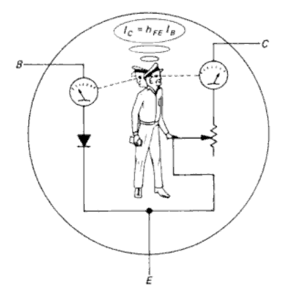
The "Transistor Man" was I believe first introduced in The Art of Electronics (great book btw, the third edition just came out). An extremely simple model of a bipolar junction transistor in the linear region states that the current going from the Base to Emitter (Ib) and the current pulled from the collector (Ic) is related by: Ic = beta * Ib. (beta is another name for hFE, at DC)
The "Transistor Man" continuously monitors Ib, multiplies by beta, and adjusts the adjustable resistor until Ic = beta * Ib.
Obviously, you can't make a resistor with a resistance below 0, so when it hits rock bottom Ic cannot reach beta * Ib, which models saturation.
Note that this "model" is insanely horrible because hFE/beta increases and decreases depending on the amount of current, by temperature, and most importantly from manufacturing tolerances. Good transistor circuits (like the AoE book teaches you how to build) work the same way regardless of hFE as long as it's in the reasonable ball park.
As Win Hill says, his "transistor man" is later discarded, and replaced by voltage-based design which eliminates hfe, relying on Vbe and Ebers-Moll equation.
This makes his book even more excellent. And the lab book for AOA goes much farther, directly exposing the many mistakes caused by "current amplifier" design philosophy based on hfe.
Look inside a BJT op-amp, where diff-input is voltage-based. And the many Current-Source sections employ the transconductance model, Vbe-based explanations, not hfe.
Heh, the actual "transistor man" is made out of voltage; he's the base voltage Vbe, and he adjusts the thickness of the depletion layer inside the emitter junction. The depletion layer observes Ib, changes its thickness in response, and this thickness then determines the value of collector current Ic. Actually Ib cannot affect Ic or vice versa, otherwise we'd just have resistor action, not transistor action.
"As a young engineer struggling with my circuit designs in the mid 60's (remember the h parameters?), a wise experienced teacher sat me down with a single sheet of paper for 30 minutes and preached the value of Ebers-Moll and Re. What's the gain of a common-emitter amplifier stage? Easy, RL / Re. And Re is 25 ohms at 1mA.
"Oops, Re = VT/IC = 25mV/IC, and changes with current, causing distortion? OK add a degenerating resistance, RE - now the gain is RL / RE+Re, and I can quickly calculate my gain and predict the distortion level for my choices of RE. Try that kind of easy analysis with the βeta approach.
"So I changed my design approach and suddenly things start working as predicted. That is to say, I could reliably engineer instead of empirically-develop my designs. I could also safely do more complex designs." - 2011 Winfield Hill http://cr4.globalspec.com/comment/720374/Re-Voltage-vs-Curre...
Also, I still want to see an actual electro-electret[2].
[1] http://amasci.com/amateur/whygnd.html
[2] http://amasci.com/elect/mcoils.html